Pin Multiplexing
Seeed Studio XIAO ESP32C3 has rich interfaces. There are 11 digital I/O that can be used as PWM pins and 4 analog inputs that can be used as ADC pins. It supports four serial communication interfaces such as UART, I2C, SPI and I2S. This wiki will be helpful to learn about these interfaces and implement them in your next projects!
Digital
Connect a pushbutton to Pin D6 and an LED to Pin D10. Then upload the following code to control the ON/OFF of LED using the pushbutton.
const int buttonPin = D6;     // pushbutton connected to digital pin 6
const int ledPin =  D10;      // LED connected to digital pin 10

int buttonState = 0;         // variable for reading the pushbutton status

void setup() {
  // initialize the LED pin as an output:
  pinMode(ledPin, OUTPUT);
  // initialize the pushbutton pin as an input:
  pinMode(buttonPin, INPUT);
}

void loop() {
  // read the state of the pushbutton value:
  buttonState = digitalRead(buttonPin);

  // check if the pushbutton is pressed. If it is, the buttonState is HIGH:
  if (buttonState == HIGH) {
    // turn LED on:
    digitalWrite(ledPin, HIGH);
  } else {
    // turn LED off:
    digitalWrite(ledPin, LOW);
  }
}
Digital as PWM
Connect an LED to Pin D10. Then upload the following code to see the LED gradually fading.
int ledPin = D10;    // LED connected to digital pin 10

void setup() {
  // declaring LED pin as output
  pinMode(led_pin, OUTPUT);
}

void loop() {
  // fade in from min to max in increments of 5 points:
  for (int fadeValue = 0 ; fadeValue <= 255; fadeValue += 5) {
    // sets the value (range from 0 to 255):
    analogWrite(ledPin, fadeValue);
    // wait for 30 milliseconds to see the dimming effect
    delay(30);
  }

  // fade out from max to min in increments of 5 points:
  for (int fadeValue = 255 ; fadeValue >= 0; fadeValue -= 5) {
    // sets the value (range from 0 to 255):
    analogWrite(ledPin, fadeValue);
    // wait for 30 milliseconds to see the dimming effect
    delay(30);
  }
}
Analog
Connect a potentiometer to Pin A0 and an LED to Pin D10. Then upload the following code to control the blinking interval of the LED by rotating the potentiometer knob.
const int sensorPin = A0;
const int ledPin =  D10;

void setup() {
  pinMode(sensorPin, INPUT);  // declare the sensorPin as an INPUT
  pinMode(ledPin, OUTPUT);   // declare the ledPin as an OUTPUT
}

void loop() {
  // read the value from the sensor:
  int sensorValue = analogRead(sensorPin);
  // turn the ledPin on
  digitalWrite(ledPin, HIGH);
  // stop the program for <sensorValue> milliseconds:
  delay(sensorValue);
  // turn the ledPin off:
  digitalWrite(ledPin, LOW);
  // stop the program for for <sensorValue> milliseconds:
  delay(sensorValue);
}
Serial
There are 2 serial interfaces on this board:
- USB Serial
- UART0 Serial
By default, USB serial is enabled, which means you can connect the board to a PC via USB Type-C and open serial monitor on Arduino IDE to view data sent via serial.
However, if you want to use UART0 as the serial, you need to connect pin D6 as the TX pin and pin D7 as RX pin with a USB-Serial adapter.
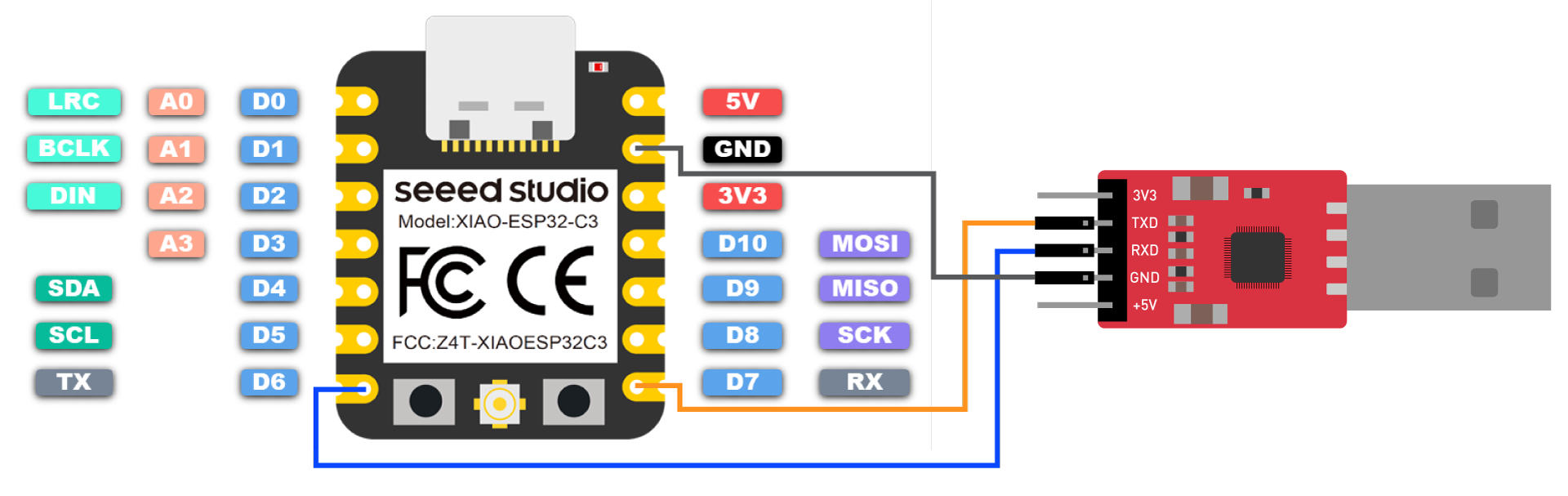
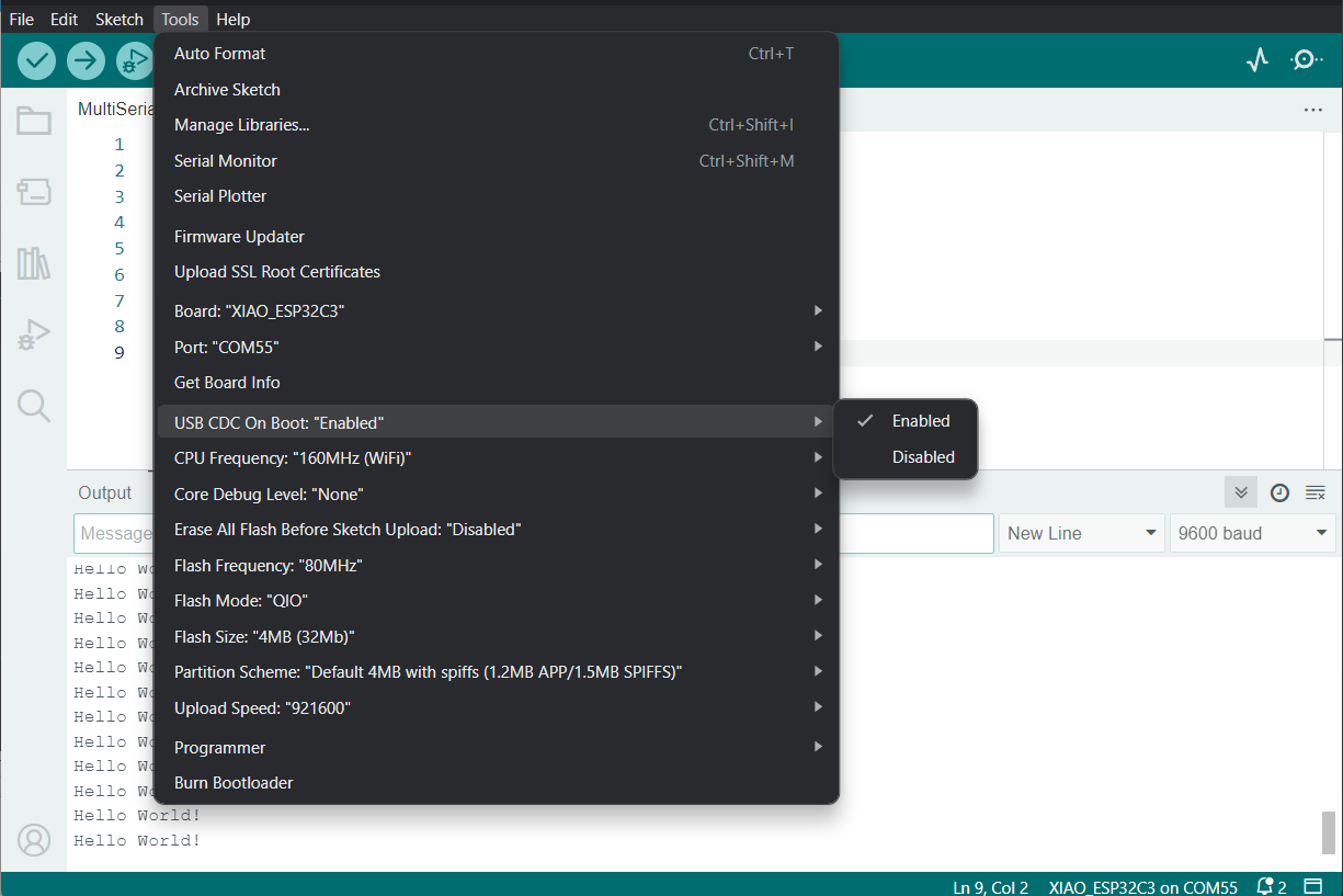
Also, you need to set USB CDC On Boot to Disabled from Arduino IDE.
NOTE: Change photo when board shows up on Arduino Board Manager
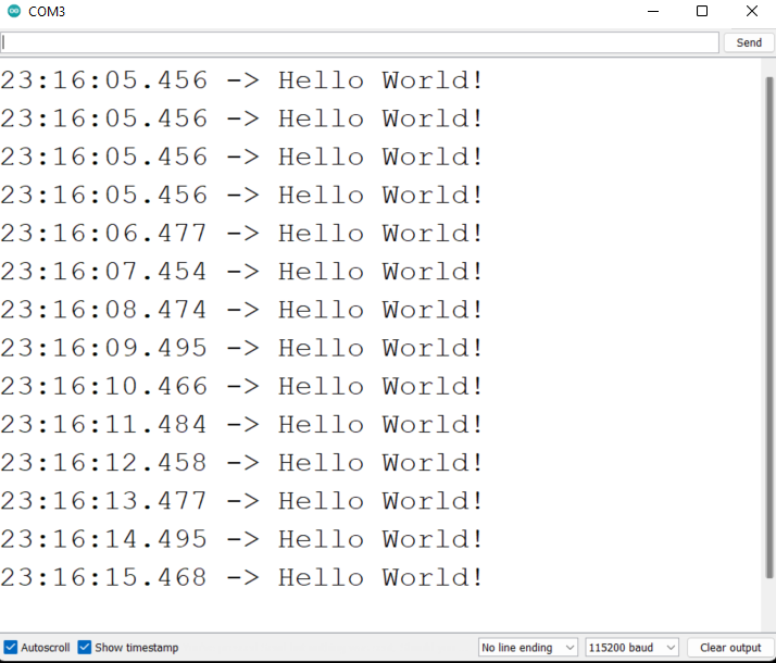
Upload the following code to Arduino IDE to send the string "Hello World!" via serial
void setup() {
    Serial.begin(115200);
    while (!Serial);
}

void loop() {
    Serial.println("Hello World!");
    delay(1000);
}
The output will be as follows on Arduino Serial Monitor
I2C
Hardware connection
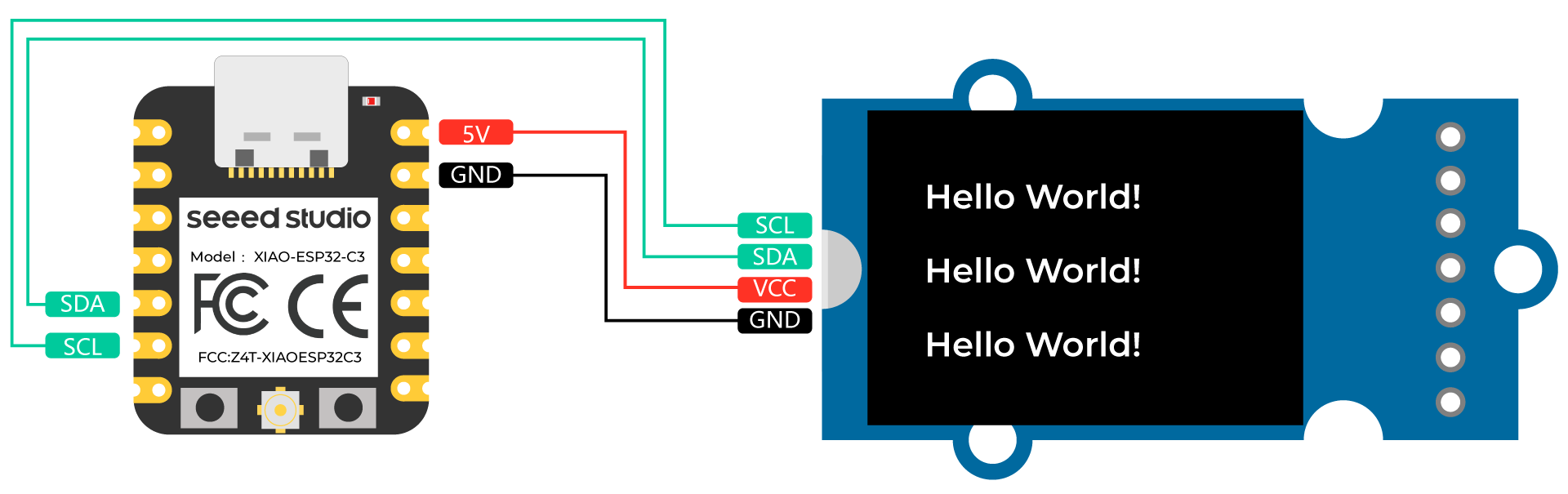
Connect a Grove - OLED Yellow&Blue Display 0.96 (SSD1315) to XIAO ESP32C3 by following the hardware connection as follows.
| Grove - OLED Yellow&Blue Display 0.96 (SSD1315) | XIAO ESP32C3 |
|---|---|
| SCL | SCL |
| SDA | SDA |
| VCC | 5V |
| GND | GND |
Software setup
Step 1. Open Arduino IDE, navigate to
Sketch > Include Library > Manage Libraries...Step 2. Search for u8g2 and install it

- Step 3. Upload the following code to display text strings on the OLED Display
//#include <Arduino.h>
#include <U8g2lib.h>

#ifdef U8X8_HAVE_HW_SPI
#include <SPI.h>
#endif
#ifdef U8X8_HAVE_HW_I2C
#include <Wire.h>
#endif

U8G2_SSD1306_128X64_NONAME_F_SW_I2C u8g2(U8G2_R0, /* clock=*/ SCL, /* data=*/ SDA, /* reset=*/ U8X8_PIN_NONE);    //Low spped I2C

void setup(void) {
  u8g2.begin();
//  u8x8.setFlipMode(1);   // set number from 1 to 3, the screen word will rotary 180
}

void loop(void) {
  u8g2.clearBuffer();                   // clear the internal memory
  u8g2.setFont(u8g2_font_ncenB08_tr);   // choose a suitable font
  u8g2.drawStr(0,15,"Hello World!");    // write something to the internal memory
  u8g2.drawStr(0,30,"Hello World!");
  u8g2.drawStr(0,40,"Hello World!");
  u8g2.sendBuffer();                    // transfer internal memory to the display
//  delay(1000);
}
SPI
Hardware connection
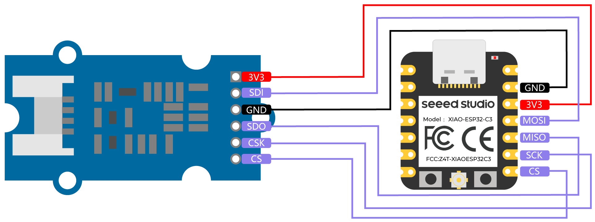
Connect a Grove - High Precision Barometric Pressure Sensor (DPS310) to XIAO ESP32C3 by following the hardware connection as follows.
| Grove - High Precision Barometric Pressure Sensor (DPS310) | XIAO ESP32C3 |
|---|---|
| 3V3 | 3V3 |
| SDI | MOSI |
| GND | GND |
| SDO | MISO |
| CSK | SCK |
| CS | CS |
Software setup
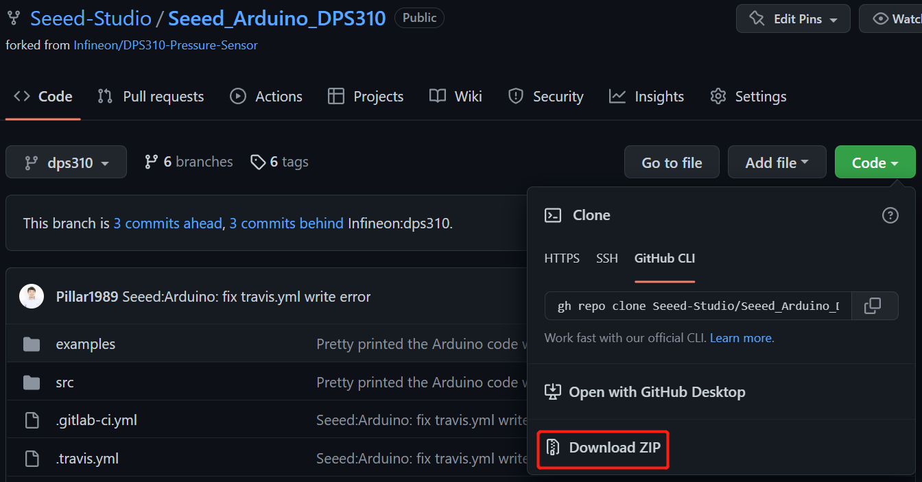
- Step 1. Download Seeed_Arduino_DPS310 Library as a zip file
- Step 2. Open Arduino IDE, navigate to
Sketch > Include Library > Add .ZIP Library...and open the downloaded zip file

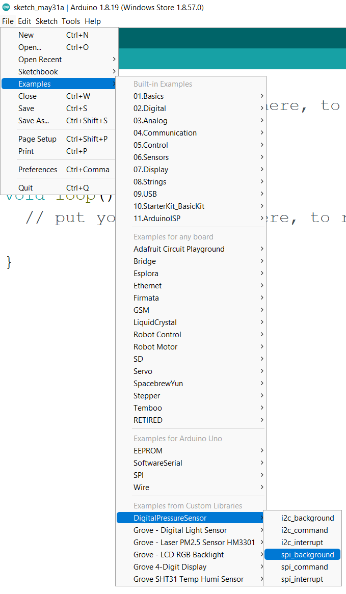
- Step 3. Navigate to
File > Examples > DigitalPressureSensor > spi_backgroundto open the spi_background example
Alternatively you can copy the code from below as well
#include <Dps310.h>

// Dps310 Opject
Dps310 Dps310PressureSensor = Dps310();

void setup() {
    //pin number of your slave select line
    //XMC2GO
    int16_t pin_cs = SS;
    //for XMC 1100 Bootkit  & XMC4700 Relax Kit uncomment the following line
    //int16_t pin_cs = 10;

    Serial.begin(9600);
    while (!Serial);


    //Call begin to initialize Dps310
    //The parameter pin_nr is the number of the CS pin on your Microcontroller
    Dps310PressureSensor.begin(SPI, pin_cs);

    //temperature measure rate (value from 0 to 7)
    //2^temp_mr temperature measurement results per second
    int16_t temp_mr = 2;
    //temperature oversampling rate (value from 0 to 7)
    //2^temp_osr internal temperature measurements per result
    //A higher value increases precision
    int16_t temp_osr = 2;
    //pressure measure rate (value from 0 to 7)
    //2^prs_mr pressure measurement results per second
    int16_t prs_mr = 2;
    //pressure oversampling rate (value from 0 to 7)
    //2^prs_osr internal pressure measurements per result
    //A higher value increases precision
    int16_t prs_osr = 2;
    //startMeasureBothCont enables background mode
    //temperature and pressure ar measured automatically
    //High precision and hgh measure rates at the same time are not available.
    //Consult Datasheet (or trial and error) for more information
    int16_t ret = Dps310PressureSensor.startMeasureBothCont(temp_mr, temp_osr, prs_mr, prs_osr);
    //Use one of the commented lines below instead to measure only temperature or pressure
    //int16_t ret = Dps310PressureSensor.startMeasureTempCont(temp_mr, temp_osr);
    //int16_t ret = Dps310PressureSensor.startMeasurePressureCont(prs_mr, prs_osr);


    if (ret != 0) {
        Serial.print("Init FAILED! ret = ");
        Serial.println(ret);
    } else {
        Serial.println("Init complete!");
    }
}


void loop() {
    uint8_t pressureCount = 20;
    float pressure[pressureCount];
    uint8_t temperatureCount = 20;
    float temperature[temperatureCount];

    //This function writes the results of continuous measurements to the arrays given as parameters
    //The parameters temperatureCount and pressureCount should hold the sizes of the arrays temperature and pressure when the function is called
    //After the end of the function, temperatureCount and pressureCount hold the numbers of values written to the arrays
    //Note: The Dps310 cannot save more than 32 results. When its result buffer is full, it won't save any new measurement results
    int16_t ret = Dps310PressureSensor.getContResults(temperature, temperatureCount, pressure, pressureCount);

    if (ret != 0) {
        Serial.println();
        Serial.println();
        Serial.print("FAIL! ret = ");
        Serial.println(ret);
    } else {
        Serial.println();
        Serial.println();
        Serial.print(temperatureCount);
        Serial.println(" temperature values found: ");
        for (int16_t i = 0; i < temperatureCount; i++) {
            Serial.print(temperature[i]);
            Serial.println(" degrees of Celsius");
        }

        Serial.println();
        Serial.print(pressureCount);
        Serial.println(" pressure values found: ");
        for (int16_t i = 0; i < pressureCount; i++) {
            Serial.print(pressure[i]);
            Serial.println(" Pascal");
        }
    }

    //Wait some time, so that the Dps310 can refill its buffer
    delay(10000);
}
- Step 4. Upload the codes and open the Serial Monitor
Note: Once you upload the codes, it will not be executed automatically until you click Serial Monitor on the upper right corner of the Arduino window.
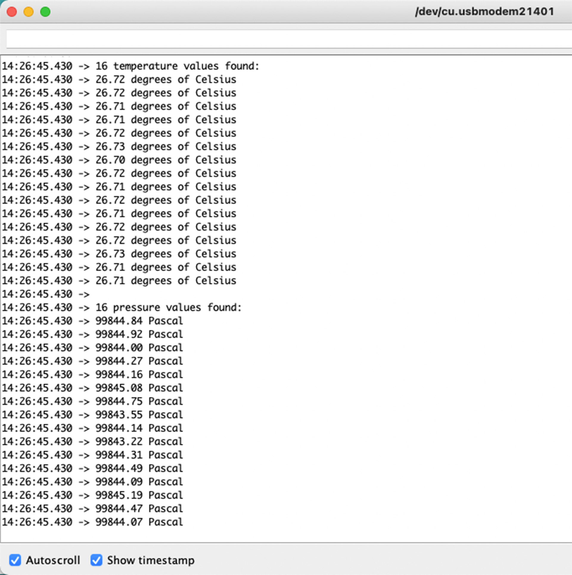
Now you will see the temperature and pressure data displayed one after the other on the serial monitor as above!