Getting Started with Seeed Studio XIAO ESP32C3
Seeed Studio XIAO ESP32C3 is an IoT mini development board based on the Espressif ESP32-C3 WiFi/Bluetooth dual-mode chip. ESP32-C3 is a 32-bit RISC-V CPU, which includes an FPU (Floating Point Unit) for 32-bit single-precision arithmetic with powerful computing power. It has excellent radio frequency performance, supporting IEEE 802.11 b/g/n WiFi, and Bluetooth 5 (LE) protocols. This board comes included with an external antenna to increase the signal strength for your wireless applications. It also has a small and exquisite form-factor combined with a single-sided surface-mountable design. It is equipped with rich interfaces and has 11 digital I/O that can be used as PWM pins and 4 analog I/O that can be used as ADC pins. It supports four serial interfaces such as UART, I2C, SPI and I2S. There is also a small reset button and a bootloader mode button on the board. XIAO ESP32C3 is fully compatible with the Grove Shield for Seeeduino XIAO and Seeeduino XIAO Expansion board except for the Seeeduino XIAO Expansion board, the SWD spring contacts on the board will not be compatible.
With regard to the features highlighted above, XIAO ESP32C3 is positioned as a high-performance, low-power, cost-effective IoT mini development board, suitable for low-power IoT applications and wireless wearable applications.
This wiki will show you how you can quickly get started with XIAO ESP32C3!
Features
- Powerful CPU: ESP32-C3, 32bit RISC-V singlecore processor that operates at up to 160 MHz
- Complete WiFi subsystem: Complies with IEEE 802.11b/g/n protocol and supports Station mode, SoftAP mode, SoftAP + Station mode, and promiscuous mode
- Bluetooth LE subsystem: Supports features of Bluetooth 5 and Bluetooth mesh
- Ultra-Low Power: Deep sleep power consumption is about 43μA
- Better RF performance: External RF antenna included
- Battery charging chip: Supports lithium battery charge and discharge management
- Rich on-chip resources: 400KB of SRAM, and 4MB of on-board flash memory
- Ultra small size: As small as a thumb(20x17.5mm) XIAO series classic form-factor for wearable devices and small projects
- Reliable security features: Cryptographic hardware accelerators that support AES-128/256, Hash, RSA, HMAC, digital signature and secure boot
- Rich interfaces: 1xI2C, 1xSPI, 1xI2S, 2xUART, 11xGPIO(PWM), 4xADC, 1xJTAG bonding pad interface
- Single-sided components, surface mounting design
Specifications comparison
| Item | Seeed Studio XIAO ESP32C3 | Seeeduino XIAO | Seeed XIAO RP2040 | Seeed XIAO BLE | Seeed XIAO BLE Sense |
|---|---|---|---|---|---|
| Processor | ESP32-C3 32-bit RISC-V @160MHz | SAMD21 M0+@48MHz | RP2040 Dual-core M0+@133Mhz | nRF52840 M4F@64MHz | nRF52840 M4F@64MHz |
| Wireless Connectivity | WiFi and Bluetooth 5 (LE) | N/A | N/A | Bluetooth 5.0/BLE/NFC | Bluetooth 5.0/BLE/NFC |
| Memory | 400KB SRAM, 4MB onboard Flash | 32KB SRAM 256KB FLASH | 264KB SRAM 2MB onboard Flash | 256KB RAM, 1MB Flash 2MB onboard Flash | 256KB RAM,1MB Flash 2MB onboard Flash |
| Built-in Sensors | N/A | N/A | N/A | N/A | 6 DOF IMU (LSM6DS3TR-C), PDM Microphone |
| Interfaces | I2C/UART/SPI/I2S | I2C/UART/SPI | I2C/UART/SPI | I2C/UART/SPI | I2C/UART/SPI |
| PWM/Analog Pins | 11/4 | 11/11 | 11/4 | 11/6 | 11/6 |
| Onboard Buttons | Reset/ Boot Button | N/A | Reset/ Boot Button | Reset Button | Reset Button |
| Onboard LEDs | Charge LED | N/A | Full-color RGB/ 3-in-one LED | 3-in-one LED/ Charge LED | 3-in-one LED/ Charge LED |
| Battery Charge Chip | Built-in | N/A | N/A | BQ25101 | BQ25101 |
| Programming Languages | Arduino | Arduino/ CircuitPython | Arduino/ MicroPython/ CircuitPython | Arduino/ MicroPython/ CircuitPython | Arduino/ MicroPython/ CircuitPython |
Hardware overview
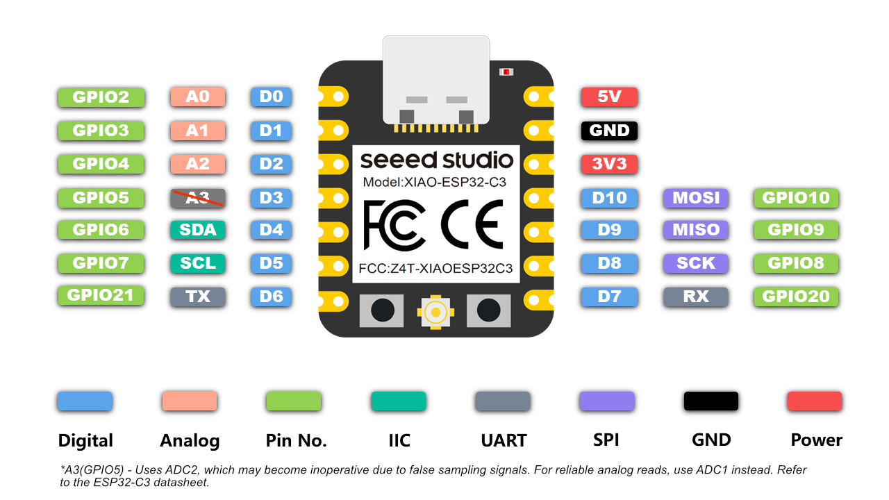
Pinout diagram
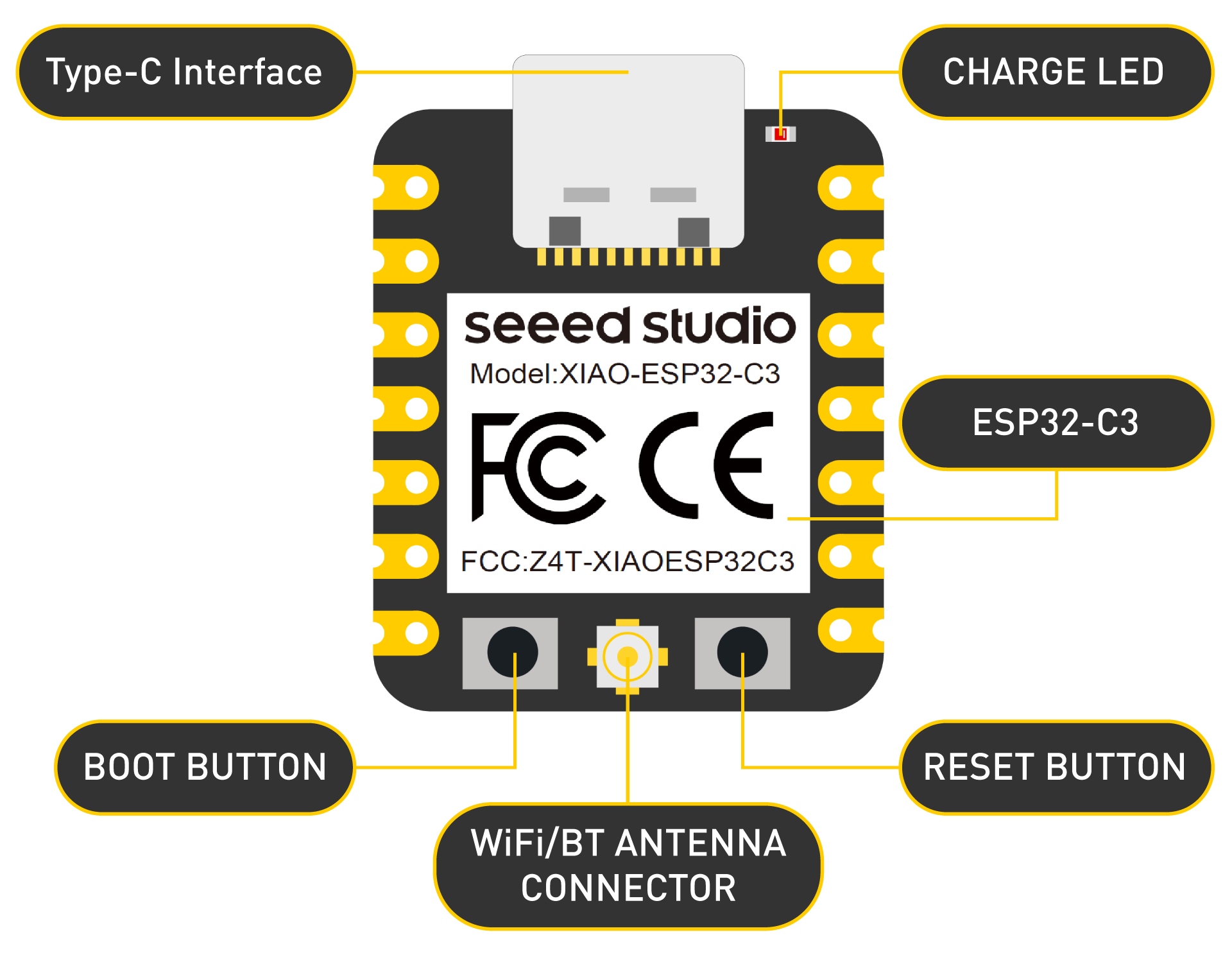
Component overview
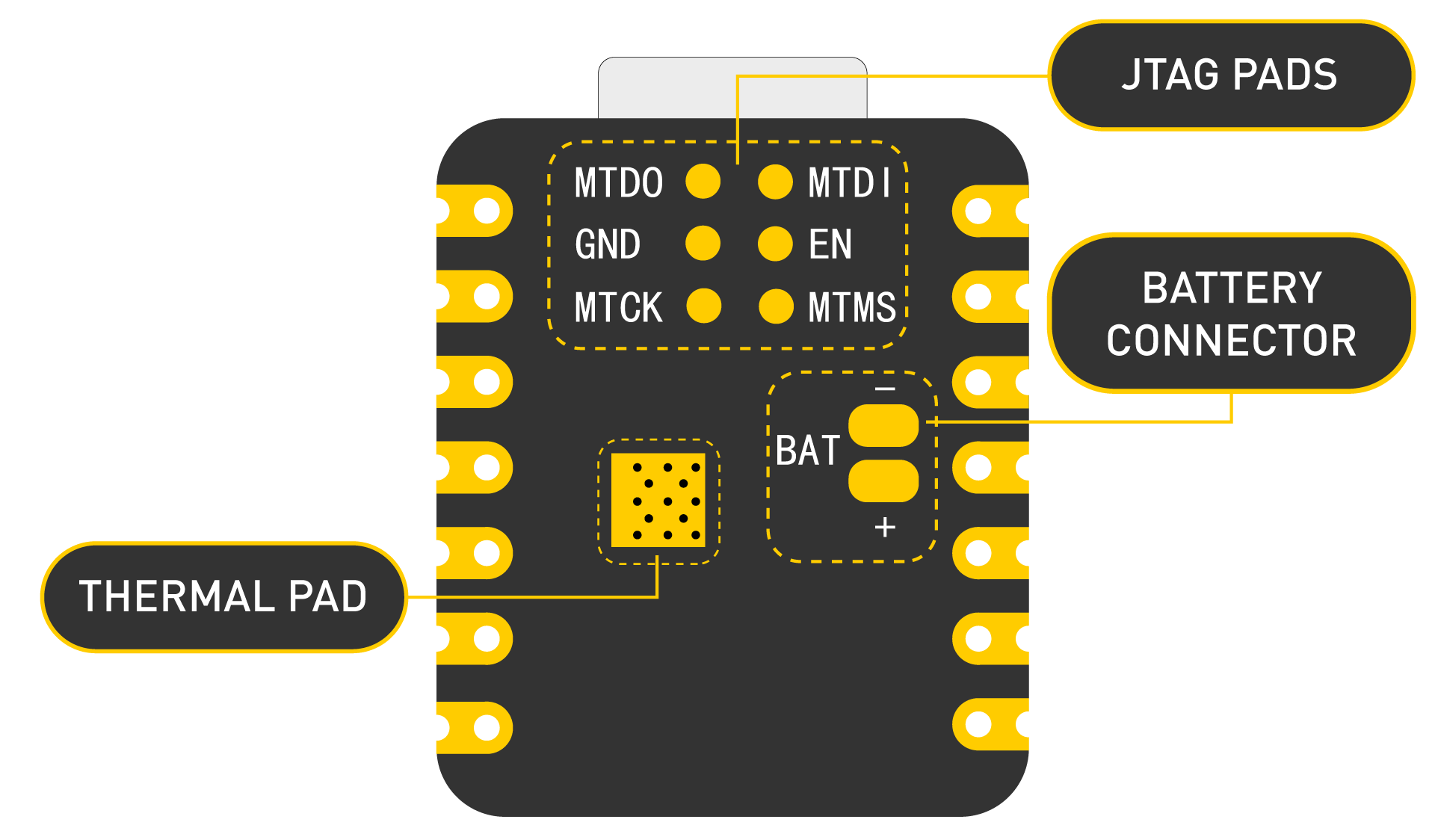
Power Pins
5V - This is 5v out from the USB port. You can also use this as a voltage input but you must have some sort of diode (schottky, signal, power) between your external power source and this pin with anode to battery, cathode to 5V pin.
3V3 - This is the regulated output from the onboard regulator. You can draw 700mA
GND - Power/data/signal ground
Getting started
First, we are going to connect XIAO ESP32C3 to the computer, connect an LED to the board and upload a simple code from Arduino IDE to check whether the board is functioning well by blinking the connected LED.
Hardware setup
You need to prepare the following:
- 1 x Seeed Studio XIAO ESP32C3
- 1 x Computer
- 1 x USB Type-C cable
Some USB cables can only supply power and cannot transfer data. If you don't have a USB cable or don't know if your USB cable can transmit data, you can check Seeed USB Type-C support USB 3.1.
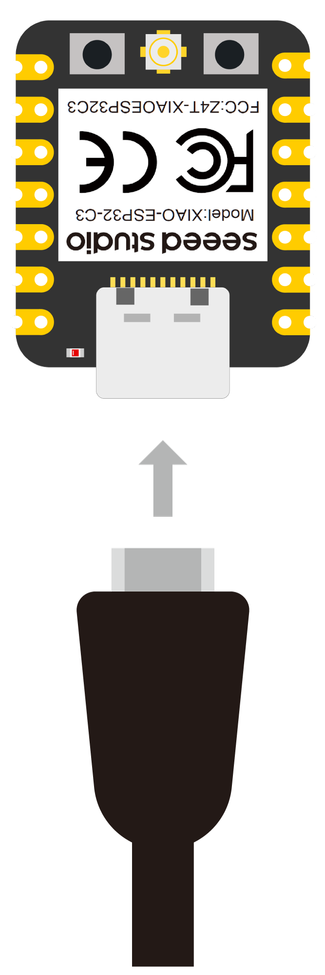
- Step 1. Connect XIAO ESP32C3 to your computer via a USB Type-C cable.
- Step 2. Connect an LED to D10 pin as follows
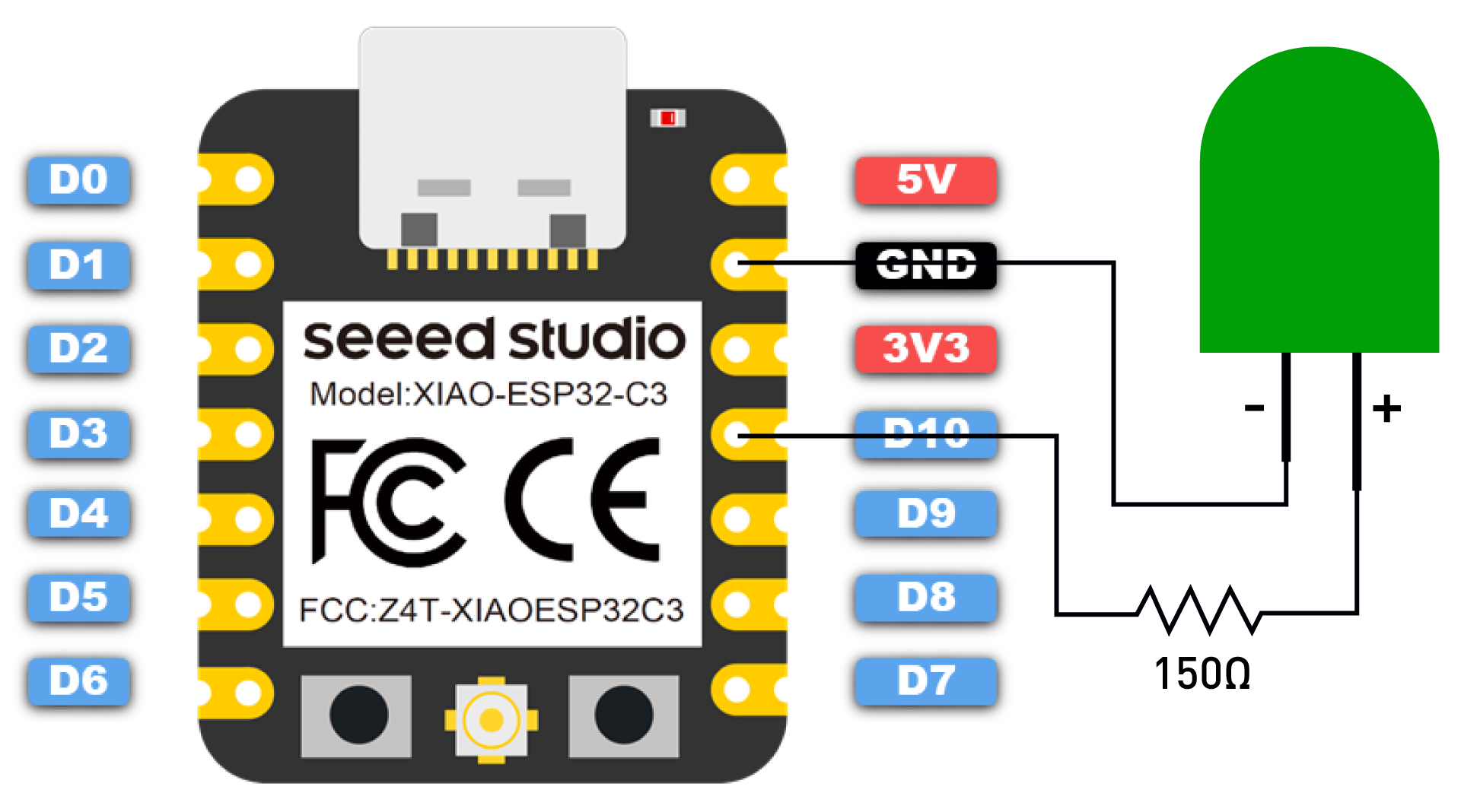
Note: Make sure to connect a resistor (about 150Ω) in series to limit the current through the LED and to prevent excess current that can burn out the LED
Software setup
- Step 1. Download and Install the latest version of Arduino IDE according to your operating system

Step 2. Launch the Arduino application
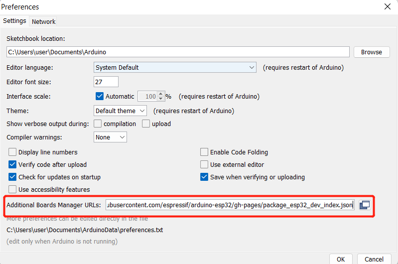
Step 3. Add ESP32 board package to your Arduino IDE
Navigate to File > Preferences, and fill "Additional Boards Manager URLs" with the url below: https://raw.githubusercontent.com/espressif/arduino-esp32/gh-pages/package_esp32_dev_index.json
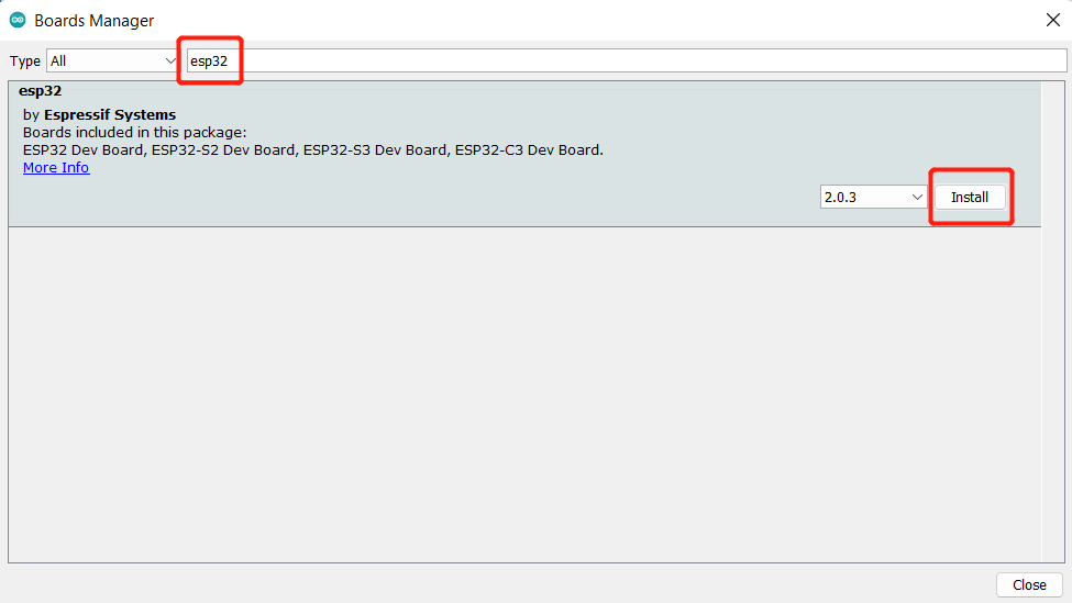
Navigate to Tools > Board > Boards Manager..., type the keyword "esp32" in the search box, select the latest version of **esp32**, and install it.
- Step 4. Select your board and port
Board
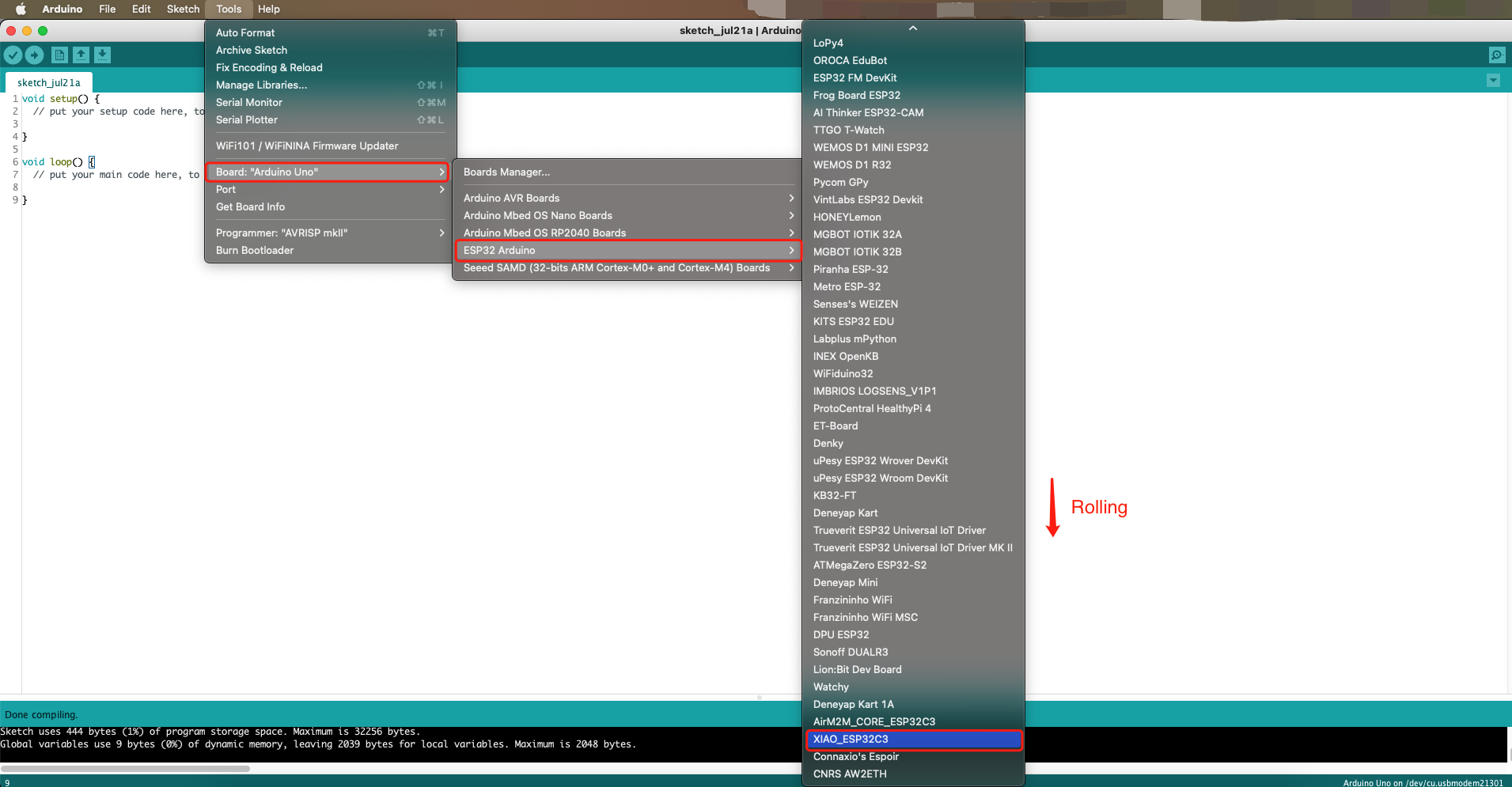
Navigate to Tools > Board > ESP32 Arduino and select "XIAO_ESP32C3". The list of board is a little long and you need to roll to the buttom to reach it.
Port
Navigate to Tools > Port and select the serial port name of the connected XIAO ESP32C3. This is likely to be COM3 or higher (COM1 and COM2 are usually reserved for hardware serial ports).
Blink the LED
- Step 1. Copy the below code to Arduino IDE
// define led according to pin diagram
int led = D10;

void setup() {
  // initialize digital pin led as an output
  pinMode(led, OUTPUT);
}

void loop() {
  digitalWrite(led, HIGH);   // turn the LED on
  delay(1000);               // wait for a second
  digitalWrite(led, LOW);    // turn the LED off
  delay(1000);               // wait for a second
}
- Step 2. Click the Upload button to upload the code to the board
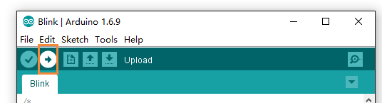
Once uploaded, you will see the connected LED blinking with a 1-second delay between each blink. This means the connection is successful and now you can explore more projects with XIAO ESP32C3!
FAQ
Q1: My Arduino IDE is stuck when uploading code to the board
You can first try to reset the board by clicking the RESET BUTTON once while the board is connected to your PC. If that does not work, hold the BOOT BUTTON, connect the board to your PC while holding the BOOT button, and then release it to enter bootloader mode.
Q2: My board is not showing up as a serial device on Arduino IDE
Follow the same answer as for Q1 above.
Q3: I want to reflash the bootloader with factory firmware
You can simply connect the board to a PC via USB Type-C and reflash the bootloader with factory firmware by using ESP RF Test Tool.
Step 1. Hold on the BOOT BUTTON and connect XIAO ESP32C3 to the PC to enter bootloader mode
Step 2. After it is connected, release the BOOT BUTTON
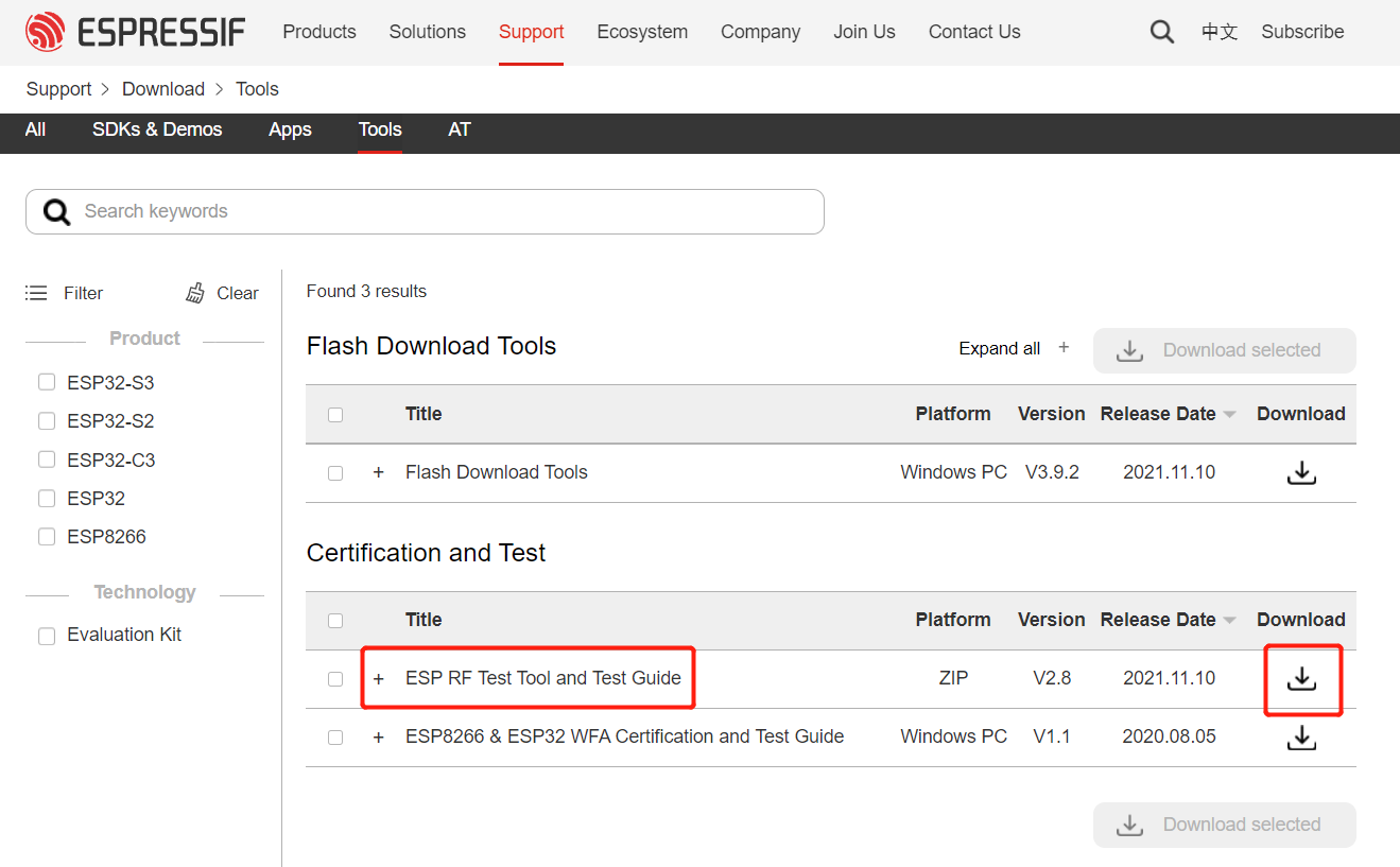
Step 3. Visit this page and download ESP RF Test Tool and Test Guide
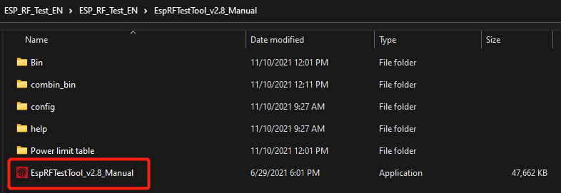
- Step 4. Extract the .zip, navigate to
ESP_RF_Test_EN\ESP_RF_Test_EN\EspRFTestTool_v2.8_Manualand open EspRFTestTool_v2.8_Manual.exe
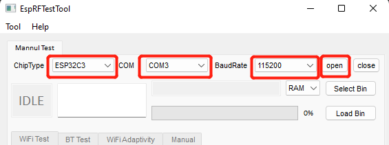
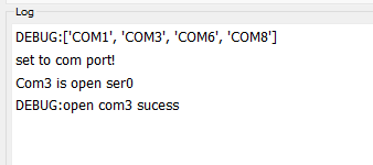
- Step 5. Select ESP32C3 as the ChipType, your COM port, 115200 as the BaudRate and click open
You will see the following output
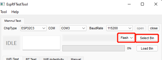
- Step 6. Select Flash and click Select Bin
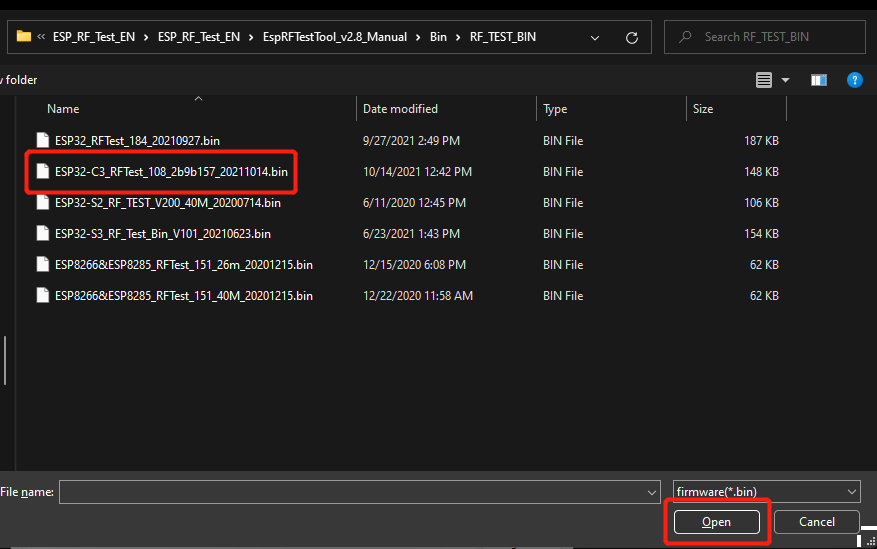
- Step 7. Select the file starting with ESP32-C3 and click Open
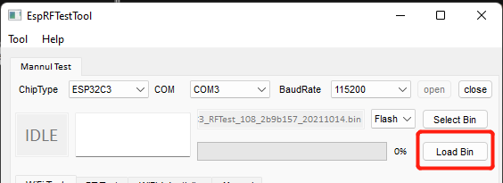
- Step 8. Finally click Load Bin
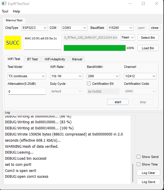
You will see the following output when flashing is successful
Resources
[PDF] ESP32C3 Datasheet
[PDF] XIAO ESP32 ROHS
Tech support
Please submit any technical issues into our forum