mmWave Fall Detection Module Pro

Introduction
60GHz mmWave Radar Sensor - Fall Detection Module Pro applies FMCW detected theory to implement simultaneous human activities detection including moving, falling, and stationary in high accuracy, providing a fully total private and secure environment, independently from other noisy influences. It is a standard biotic radar system in private property surveillance, falling caution, elderly health care, performing well in home, hotel, as well as hospital. In this wiki, we will introduce you how to utilize it.
Application
- Smart home
- Health care
- Fall detection
- Smart hotel
- Medical assistants
Feature
- Enabled theory: Implement radar detection based on 60GHz FM continuous wave signals
- Enhanced detecting algorithm: Sense and output simultaneously human activities including moving, falling, and stationary in the self-adaption environment
- Perfect privacy protection: Apply FMCW monitoring technology to provide surveillance capabilities without identification
- Health-friendly working status: Output power as low as harmless to the human body
- High stability: Independ from temperature, humidity, noise, airflow, dust, light, and other environmental influences
- High measured accuracy: Achieve fall detection accuracy up to 90% and achieve presence awareness function accuracy up to 90 %
- High flexibility hardware design radar: Support secondary development, adapt to various scenarios applications
Specification
| Detection angle and distance | Minimum | Typical | Maximum | Unit |
|---|---|---|---|---|
| Content Minimum Typical Maximum Units | ||||
| Radius of movement of people detection [1] | 6 | metre | ||
| Fall monitoring radius [2] | 2.5 | metre | ||
| Radar detection angle (horizontal) | 100 | degree | ||
| Radar detection angle (pitch) | 100 | degree | ||
| Note: [1][2] Radar hang height 2.8 m, radius of radar projection. | ||||
| Electrical characteristics | ||||
| Operating voltage (VCC) | 4.5 | 5 | 6 | V |
| Operating current (ICC) | 90 | 93 | 100 | mA |
| Operating temperature (TOP) | -20 | 60 | ℃ | |
| Storage temperature (TST) | -40 | 80 | ℃ | |
| RF performance | ||||
| Operating frequency (fTX) | 58 | 63.5 | GHz | |
| Transmitted power (Pout) | 6 | dBm |
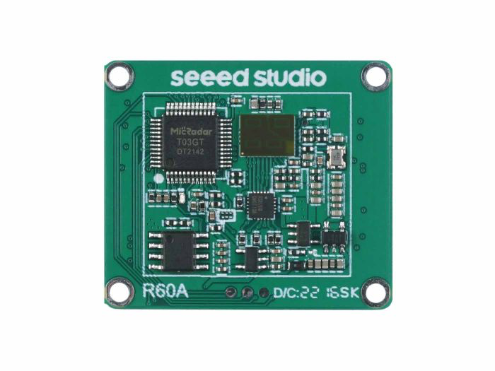
Hardware Overview
Before everything starts, it is quite essential to have some basic parameters of the product. The following table provides information about the characteristics of 60GHz mmWave Breathing and Heartbeat Module.
Getting Started
Arduino Library Overview
If this is your first time using Arduino, we highly recommend you to refer to Getting Started with Arduino.
The library code used in this example can be downloaded by clicking the icon below.
![]()
Function
Before we get started developing a sketch, let's look at the available functions of the library.
void recvRadarBytes()—— This function takes the length of the current frame returned by radar. The frames are stored in an array according to that length. Input parameters: None Return value: Nonevoid Situation_judgment(byte inf[])—— This function is mainly used to resolve the current motion of the detector. The motion situation includes whether there is someone, whether the person's motion is close or far away, whether there is a pattern, etc.. The information will be printed out through the serial port. At the same time, some data content about the features will be output. The larger the value of the features, the greater the magnitude of the human motion, and the user can develop specific functions to be completed according to the magnitude of the motion accordingly. Input parameters:byte inf[]—— Data frames sent by the radar.Return value: None
void Fall_Detection(byte inf[])—— This function completes the decoding of the fall detection information returned by the radar and prints the results of the radar detection through the serial port. fall detection information includes: the presence or absence of falls, the confidence level of the fall, the location of the fall and the point cloud data. There will be some functionality not yet implemented here and you may not receive this message until the functionality is implemented, please refer to this document for the progress of implementation. Input parameters:byte inf[]—— Data frames sent by the radar.Return value: None
void SerialInit()—— Set the radar serial port baud rate to 115200. If it is a Seeeduino board, set the soft serial port to RX: 2, TX: 3. Input parameters: None Return value: None
Default Variables
#define MESSAGE_HEAD 0x53       //Data frame header
#define MESSAGE_TAIL 0x54       //Data frame tail

#define HUMAN_PSE_RADAR 0x80    //Human presence data

#define PRESENCE_INF 0x01       //Presence Information
#define SOMEONE_HERE 0x01       //Someone here
#define NOONE_HERE 0x00         //Noone here

#define MOVE_INF 0x02           //Campaign Information
#define NONE 0x00               //None
#define STATIONARY 0x01         //A person is stationary
#define MOVEMENT 0x02           //A person in motion

#define BODY_SIG 0x03           //Body movement information

#define DISTANCE 0x04           //Distance from the person being detected

#define MOVESPEED 0x06          //Speed of character movement

#define FALL_DETECTION 0x83     //Fall data markers

#define FALL_STATE 0x01         //Fall status marker
#define NO_FALL 0x00            //No falls detected
#define FALLING 0x01            //Fall detected

#define FALL_POTENTIAL 0x02     //Confidence level for falls

#define FALL_LOCATION 0x03      //Location of the fall

#define POINTCLOUD_DATA 0x04    //Point cloud data

const byte MsgLen = 12;         //Data frame maximum length value
byte dataLen = 12;              //Real data frame length
byte Msg[12];                   //Set a fixed array to receive the first data
boolean newData = false;        //Controlling the reception of a new set of data
Installation
Step 1. You need to Install an Arduino Software.

Step 2. Launch the Arduino application.
Step 3. Select your development board model and add it to the Arduino IDE.
If you want to use Seeeduino V4.2 for the later routines, please refer to this tutorial to finish adding.
If you want to use Seeeduino XIAO for the later routines, please refer to this tutorial to finish adding.
If you want to use XIAO RP2040 for the later routines, please refer to this tutorial to finish adding.
If you want to use XIAO BLE for the later routines, please refer to this tutorial to finish adding.
Step 4. Install the Arduino code library.
Start by getting the code base from GitHub and downloading it to your local computer.
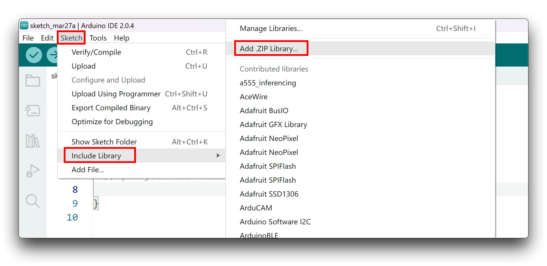
Since you have downloaded the zip Library, open your Arduino IDE, click on Sketch > Include Library > Add .ZIP Library. Choose the zip file you just downloaded,and if the library install correct, you will see Library added to your libraries in the notice window. Which means the library is installed successfully.
Arduino Example
Now that we have our library installed and we understand the basic functions, let's run some examples for our XIAO BLE to see how it behaves.
Materials Required
Before completing the following examples, you will need to prepare the following materials.
|  |  |
| 60GHz mmWave Radar Sensor | Seeed XIAO BLE nRF52840 Sense | 2mm to 2.54mm Pitch Ribbon Cable |
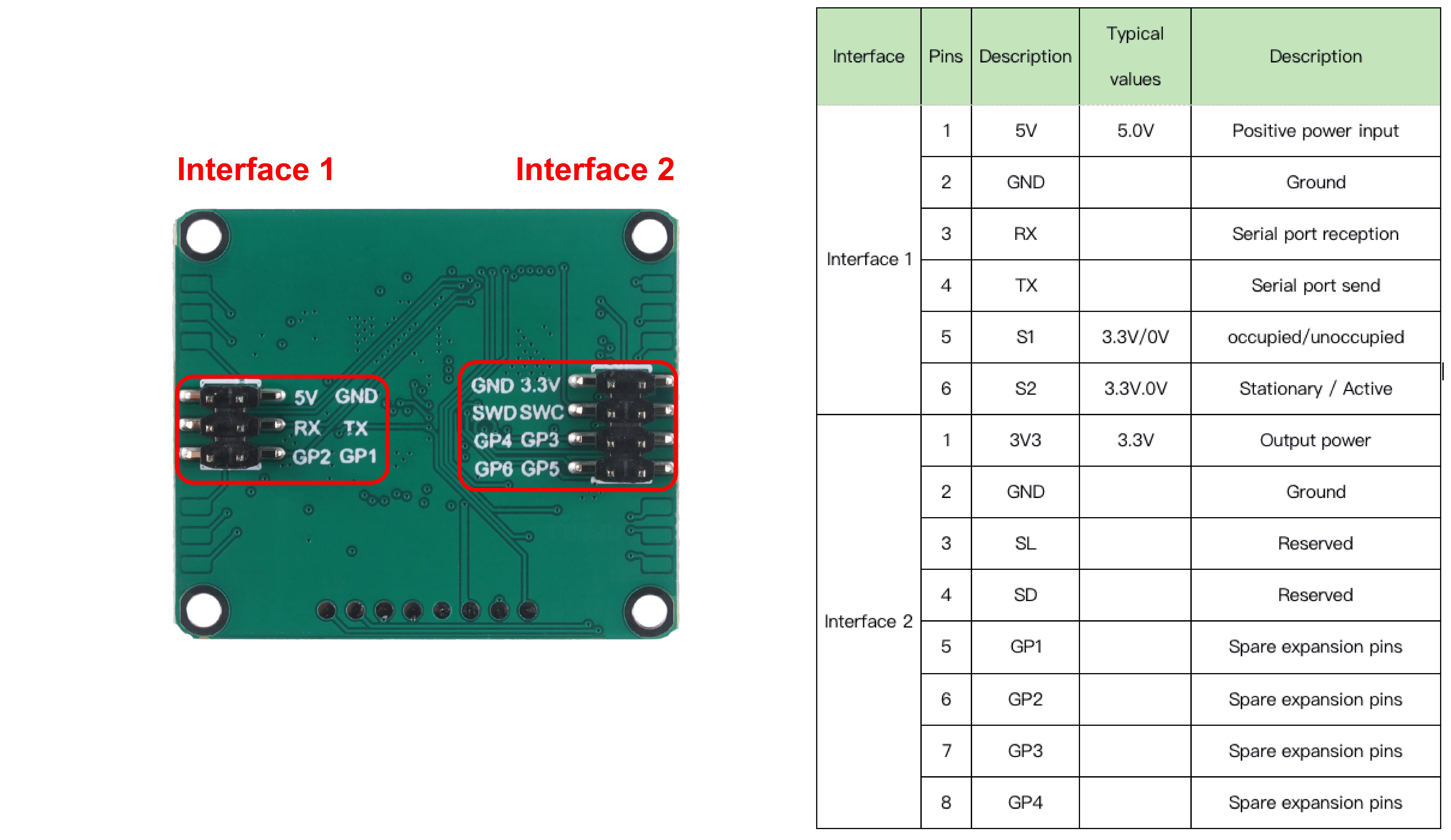
Step 1. Connect the device to the computer through the main board. The wiring diagram is shown in the table below.
 | |||
| Radar Sensor | Main Board | ||
| 5V | --> | 5V | |
| GND | --> | GND | |
| RX | --> | D6 | |
| TX | --> | D7 | |
Step 2. In the menu bar in the upper left corner of the Arduino IDE, select tool, choose the type of development board you are using, and select the corresponding serial port.
If you are using MacOS, the serial port name of the device will often start with /dev/cu.usbmodem xxx, ending with the name of the device. If you are using Windows, the device's serial port name will often begin with COM, again ending with the device's name.

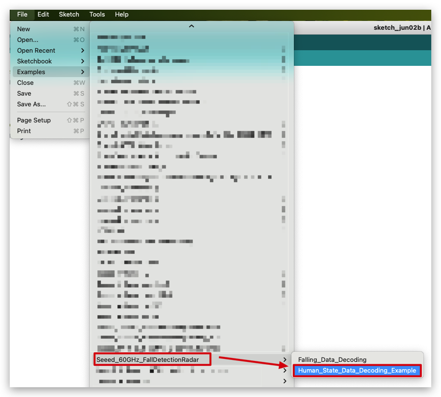
In this example, we will demonstrate how the radar works with our popular product XIAO BLE.
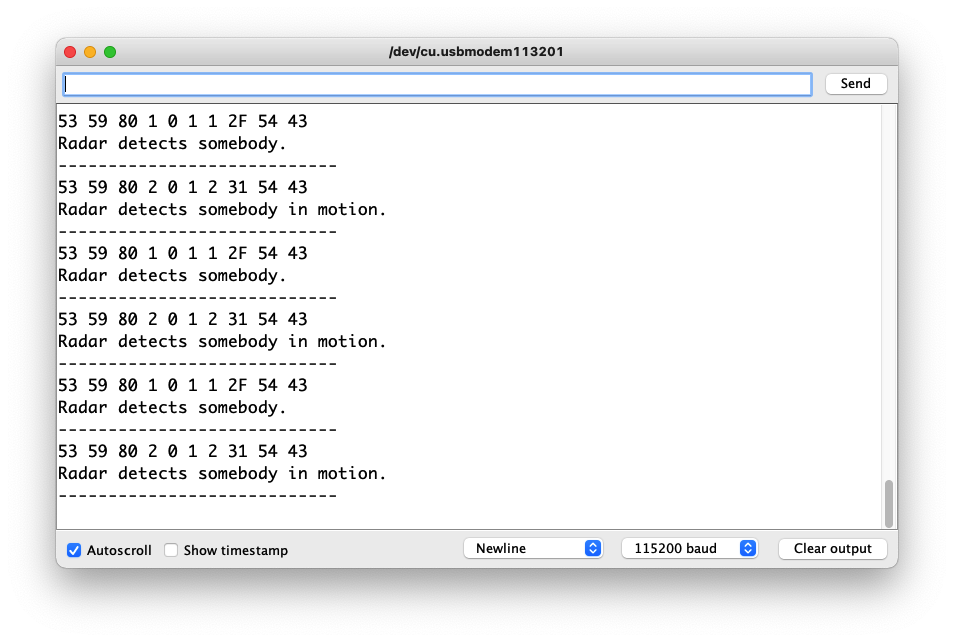
Demo1 Decode built-in radar algorithm data output human presence information
The radar has a complete set of built-in algorithms that can directly output the human presence information obtained by the radar judgment. This routine will describe how to print out the human presence information detected by the radar directly through the serial port via code.
The code in this example is as follows.
//Human_State_Data_Decoding_Example.ino

#include <60ghzfalldetection.h>

FallDetection_60GHz radar;

void setup()
{
  radar.SerialInit();
  Serial.begin(115200);
  delay(1500);
  Serial.println("Readly");
}

void loop()
{
 radar.recvRadarBytes();                       //Receive radar data and start processing
 if (radar.newData == true) {                  //The data is received and transferred to the new list dataMsg[]
    byte dataMsg[radar.dataLen+3] = {0x00};
    dataMsg[0] = 0x53;                         //Add the header frame as the first element of the array
    for (byte n = 0; n < radar.dataLen; n++)dataMsg[n+1] = radar.Msg[n];  //Frame-by-frame transfer
    dataMsg[radar.dataLen+1] = 0x54;
    dataMsg[radar.dataLen+2] = 0x43;
    radar.newData = false;                     //A complete set of data frames is saved

    //radar.ShowData(dataMsg);                 //Serial port prints a set of received data frames
    radar.Situation_judgment(dataMsg);         //Use radar built-in algorithm to output human motion status
  }

}
In the setup() code, we turn on the Serial port and the Serial1 port on the XIAO BLE. Serial is used for data printing and Serial1 is used for communication between the XIAO BLE and the radar. According to the baud rate of the radar, we set the baud rate of both serial ports to 115200. When it is ready, the serial monitor will print Ready.
adar.recvRadarBytes();
 if (radar.newData == true) {
    byte dataMsg[radar.dataLen+3] = {0x00};
    dataMsg[0] = 0x53;
    for (byte n = 0; n < radar.dataLen; n++)dataMsg[n+1] = radar.Msg[n];
    dataMsg[radar.dataLen+1] = 0x54;
    dataMsg[radar.dataLen+2] = 0x43;
    radar.newData = false;
}
In the loop, we first use the recvRadarBytes() function to store the data sent by the radar in a fixed-length array Msg[12]. Due to the complexity of radar data, a single fixed-length array is not sufficient for our data processing task, so we need an array that can be resized to store the set of data according to the current data frame length. This is where the array dataMsg[dataLen] comes into play, seeing that dataLen is the actual length of the current data frame. As you can see, we are adding frames to the array of dataMsg here, which is adding the first and last frames to it.
radar.Situation_judgment(dataMsg);
When the dataMsg list is completely obtained, it will be used as the parameter of the Situation_judgment() function to complete the output of human presence information, and the output result will be printed directly on the serial monitor.
Upload program. Opening your serial monitor to a baud rate of 115200 should show the result. The output should look something like the below image.
If you want to see what data is returned by radar, you can uncomment radar.ShowData(dataMsg);, which will output the complete set of received data frames through the serial monitor.
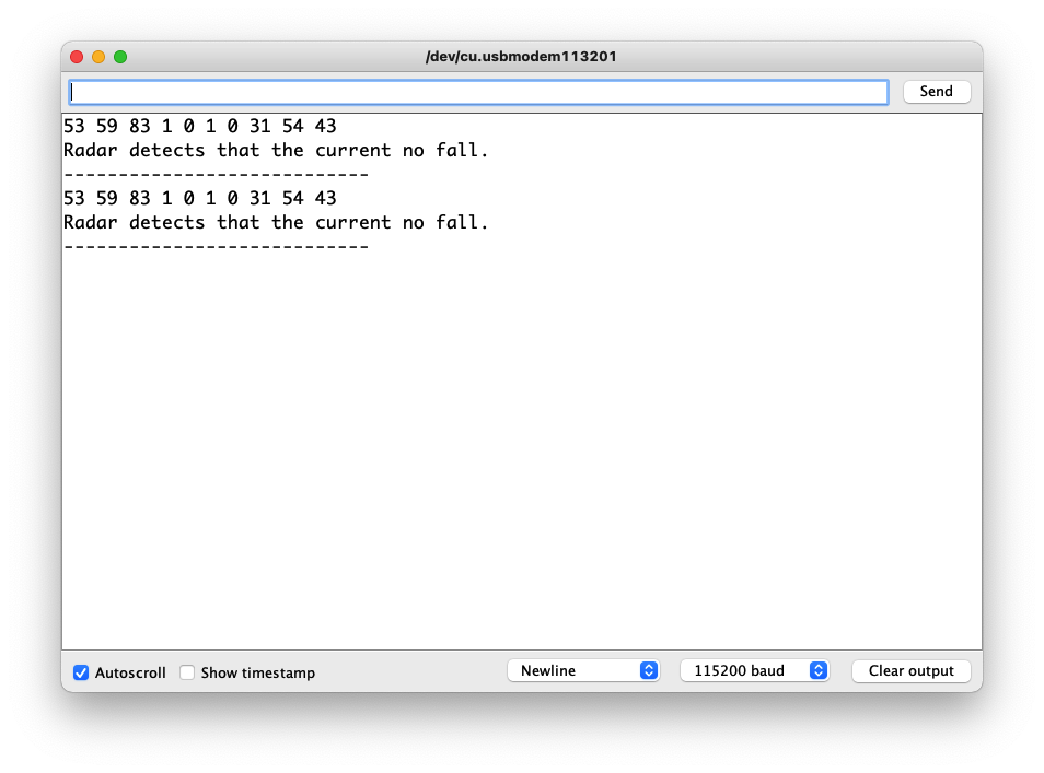
Demo 2 Get radar-reported falls information
Obtaining information on the detection of a person's fall is a special feature of this radar. We can complete the output of detection data by the following code example.
The code in this example is as follows.
//Falling_Data_Decoding.ino

#include <60ghzfalldetection.h>

FallDetection_60GHz radar;

void setup()
{
  radar.SerialInit();
  Serial.begin(115200);
  delay(1500);
  Serial.println("Readly");
}

void loop()
{
 radar.recvRadarBytes();                       //Receive radar data and start processing
 if (radar.newData == true) {                  //The data is received and transferred to the new list dataMsg[]
    byte dataMsg[radar.dataLen+3] = {0x00};
    dataMsg[0] = 0x53;                         //Add the header frame as the first element of the array
    for (byte n = 0; n < radar.dataLen; n++)dataMsg[n+1] = radar.Msg[n];  //Frame-by-frame transfer
    dataMsg[radar.dataLen+1] = 0x54;
    dataMsg[radar.dataLen+2] = 0x43;
    radar.newData = false;                     //A complete set of data frames is saved

    //radar.ShowData(dataMsg);                 //Serial port prints a set of received data frames
    radar.Fall_Detection(dataMsg);         //Use radar built-in algorithm to output human motion status
  }

}
radar.Fall_Detection(dataMsg);
When the dataMsg list is completely obtained, it will be used as the parameter of the Fall_Detection(dataMsg); function to complete the output of falling data, and the output result will be printed directly on the serial monitor.
Upload program. Opening your serial monitor to a baud rate of 115200 should show the result. The output should look something like the below image.
If you want to see what data is returned by radar, you can uncomment radar.ShowData(dataMsg);, which will output the complete set of received data frames through the serial monitor.
Demo 3 Sending data to radar
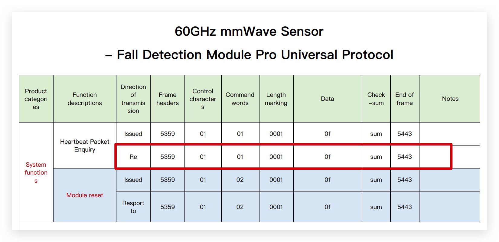
Radar opens a very large number of interfaces for us to get information and to set the radar working mode, etc. This routine will instruct the user how to use the user manual to send data messages to the radar to adjust the parameters of the radar or to obtain the desired data information.
Step 1. Obtain data frames based on the desired query.
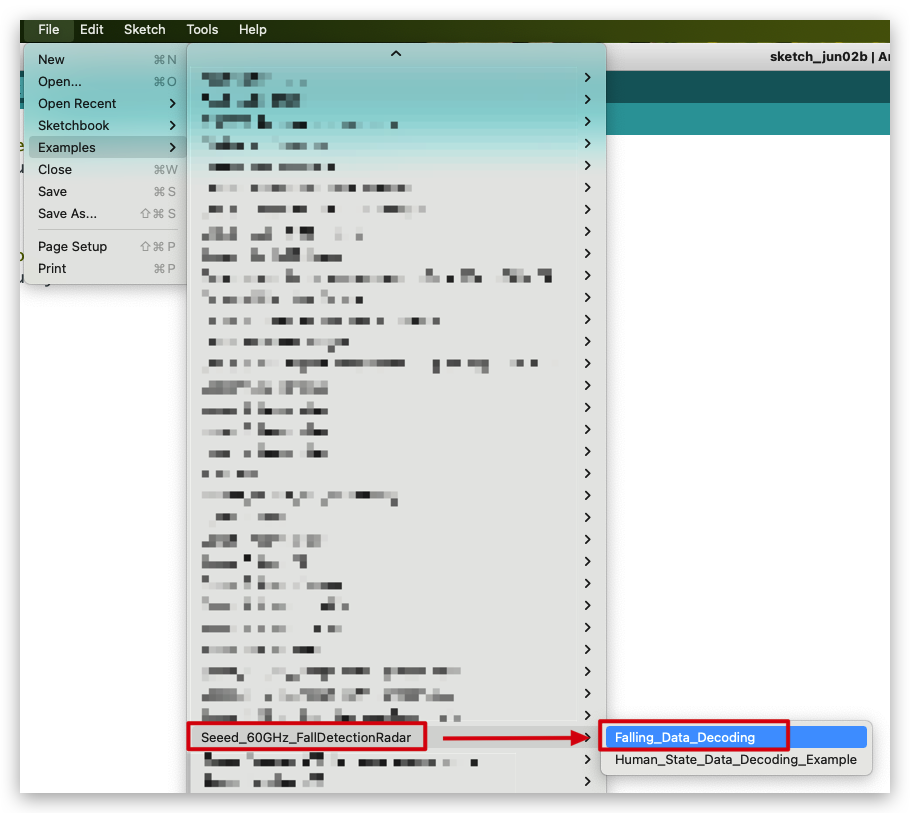
Download the Universal Protocol in the Resource area, and in the table, find the content of the frames you need to query or set up, and organize them.
In this example, suppose you want to query the radar for heartbeat packet data, then you first need to find the frame corresponding to the table.
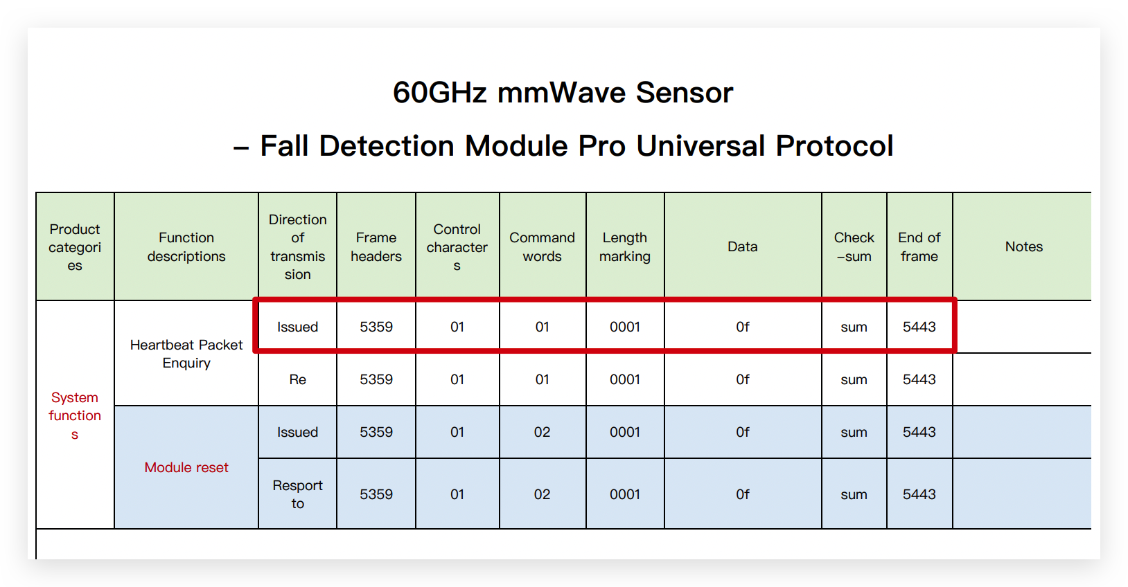
The query form shows that to get the data of the heartbeat packet, the data frame to be sent to the radar is:
0x53 0x59 0x01 0x01 0x00 0x01 0x0f $<sum> 0x54 0x43
The environment variable $<sum> refers to the checksum field, how to get it we will introduce in the step 2..
Step 2. Get the checksum field. The checksum field is calculated as follows:
Frame headers + Control charaters + Command words + Length marking + Data, then take the lower eight bits and convert to hexadecimal numbers.
For example, in step 1., the frame we want to send is:
0x53 0x59 0x01 0x01 0x00 0x01 0x0f $<sum> 0x54 0x43
So,
Frame headers + Control charaters + Command words + Length marking + Data =
0x53 + 0x59 + 0x01 + 0x01 + 0x00 + 0x01 + 0x0f =
0xBE =
0000 0000 1011 1110 (Binary)
Then take the lower eight digits of it.
1011 1110 (Binary) =
0xBE
So the check sum field in the frame we should send to the radar is 0xBE.
Step 3. Send data frames to the radar.
Connect the radar directly to the computer's usb port via a UART to USB device. The wiring is shown in the table below.
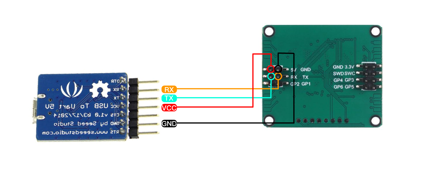 | |||
| Radar Sensor | Main Board | ||
| 5V | --> | 5V | |
| GND | --> | GND | |
| RX | --> | TX | |
| TX | --> | RX | |
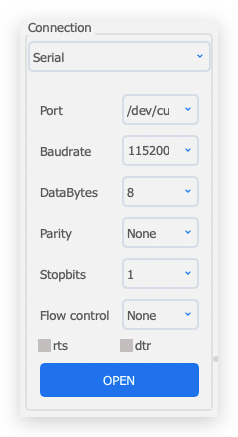
Use a software like serial debugging assistant to select the serial port where the radar is located.
60GHz radar needs 5V power supply, otherwise the radar may not work properly.
After a successful connection, you will see the radar sending a steady stream of messages.
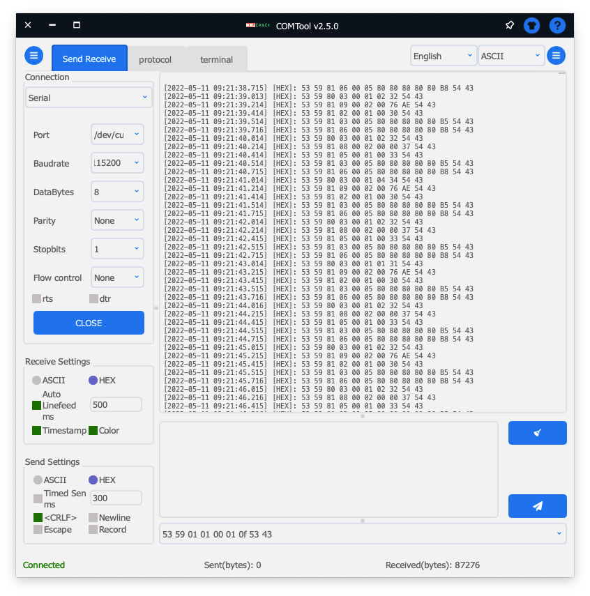
Paste the complete data frame we obtained in step 2. onto the send area of the software. Then click Send.
0x53 0x59 0x01 0x01 0x00 0x01 0x0f 0xBE 0x54 0x43
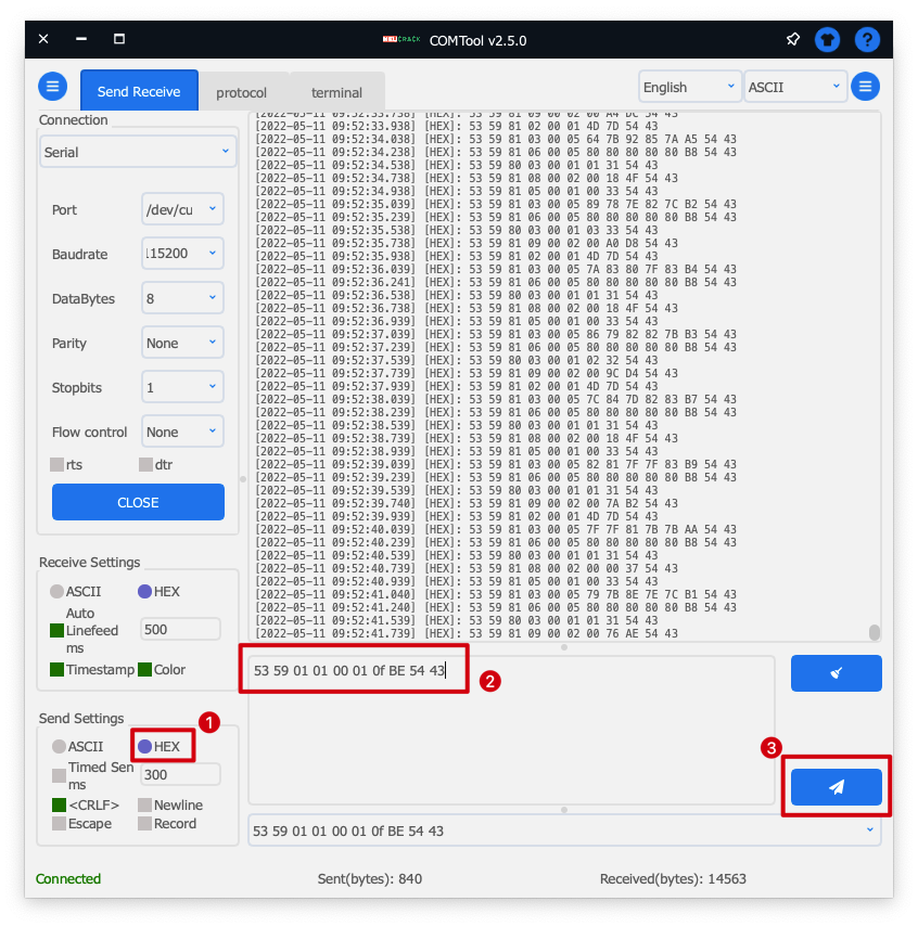
You can look out for a set of data returned. This set of data is the information obtained after the query. If you send data that adjusts the parameters of the radar, it will also return such information.
If you choose ASCII as the format for sending data, each data set needs to be prefixed with 0x. If you choose HEX, then each set of data does not need to be prefixed with 0x.
Troubleshooting
FAQ1: How to apply the code to Seeeduino (or Arduino)?
Because of the different hardware design, the serial port of XIAO series or Wio Terminal are named Serial1, while Seeeduino or Arduino need to use soft serial port. If you want to use the radar for Seeeduino, you can change the soft serial port or use pins 2 (RX) and 3 (TX).

FAQ2: What should I do if XIAO BLE and Radar collect data for a long time and cannot upload the code?
At this time, you can use your finger to lightly press the reset button on top of XIAO BLE to re-upload the program to run.
FAQ3: Why can't I receive the content on certain forms
Some of the features we are working on are in intensive development.
Resources
- [PDF] Universal Protocol
- [PDF] User manual
- [PDF] Seeed Studio MMWave Sensor Case Design
Tech Support
Please do not hesitate to submit the issue into our forum.