Grove - IMU 10DOF

Grove - IMU 10DOF is a combination of Grove - IMU 9DOF and Grove - Barometer Sensor (BMP180). This module is base on MPU-9250 and BMP180, the MPU-9250 is a 9-axis MotionTracking device that combines a 3-axis gyroscope, 3-axis accelerometer, 3-axis magnetometer and a Digital Motion Processor(DMP), and BMP180 is a high precision, ultra-low power digital pressure sensors for consumer applications. This module is very suitable for the application of smartphones, tablets and wearable devices.
Specifications
- I2C interface
- MPU-9250 I2C address selectable
- Low Power Consumption
- 400kHz Fast Mode I2C for communicating with all registers
- Digital-output X-, Y-, and Z-Axis angular rate sensors (gyroscopes) with a user-programmable full-scale range of ±250, ±500, ±1000, and ±2000°/sec
- Digital-output 3-Axis accelerometer with a programmable full scale range of ±2g, ±4g, ±8g and ±16g
- Digital-output magnetometer with a full scale range of ±4800uT
- Digital-output barometer with range of 300 ~ 1100hPa(+9000m ~ -500m relating to sea level)
- Dimensions: 25.43mm x 20.35mm
- I2C Address: default 0x68, refer to Hardware Overview to change to 0x69.
If you want to use multiplue I2C devices, please refer to [Software I2C](https://wiki.seeedstudio.com/Arduino_Software_I2C_user_guide/)
More details about Grove modules please refer to [Grove System](https://wiki.seeedstudio.com/Grove_System/)
Platforms Supported
| Arduino | Raspberry Pi |
|---|---|
|
|
The platforms mentioned above as supported is/are an indication of the module's software or theoritical compatibility. We only provide software library or code examples for Arduino platform in most cases. It is not possible to provide software library / demo code for all possible MCU platforms. Hence, users have to write their own software library.
Hardware Overview


- 1:MPU-9250 I2C address select Pad, default connected a and b address is 0x68, if connect b and c address is 0x69
- 2:MPU-9250 interrupt pin, the interrupt should be configured, available interrupt sources are: motion detection, fifo overflow, data ready, i2c master error
Getting started
We will provide an example here to show you how to use this sensor.
Play with Arduino
Hardware
- Step 1. Prepare the below stuffs:
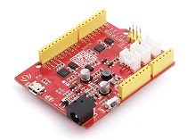
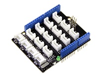
| Seeeduino V4.2 | Base Shield | Grove-IMU_10DOF |
|---|---|---|
|
|
|
| Get One Now | Get One Now | Get One Now |
- Step 2. Connect Grove-IMU_10DOF to port I2C of Grove-Base Shield.
- Step 3. Plug Grove - Base Shield into Seeeduino.
- Step 4. Connect Seeeduino to PC via a USB cable.

If we don't have Grove Base Shield, We also can directly connect this module to Seeeduino as below.
| seeeduino_v4 | Grove-IMU_10DOF |
|---|---|
| 5V | VCC |
| GND | GND |
| SDA | SDA |
| SCL | SCL |
Software
Step 1. Download the library from Github.
Step 2. Refer How to install library to install library for Arduino.
Step 3. Open the code directly by the path:File -> Example -> IMU_10DOF_Test.
Here is a part of the code:
void setup()
{
    // join I2C bus (I2Cdev library doesn't do this automatically)
    Wire.begin();

    // initialize serial communication
    // (38400 chosen because it works as well at 8MHz as it does at 16MHz, but
    // it's really up to you depending on your project)
    Serial.begin(38400);

    // initialize device
    Serial.println("Initializing I2C devices...");
    accelgyro.initialize();
    Barometer.init();

    // verify connection
    Serial.println("Testing device connections...");
    Serial.println(accelgyro.testConnection() ? "MPU9250 connection successful" : "MPU9250 connection failed");

    delay(1000);
    Serial.println("     ");

    //  Mxyz_init_calibrated ();

}

void loop()
{

    getAccel_Data();
    getGyro_Data();
    getCompassDate_calibrated(); // compass data has been calibrated here
    getHeading();               //before we use this function we should run 'getCompassDate_calibrated()' frist, so that we can get calibrated data ,then we can get correct angle .
    getTiltHeading();

    Serial.println("calibration parameter: ");
    Serial.print(mx_centre);
    Serial.print("         ");
    Serial.print(my_centre);
    Serial.print("         ");
    Serial.println(mz_centre);
    Serial.println("     ");


    Serial.println("Acceleration(g) of X,Y,Z:");
    Serial.print(Axyz[0]);
    Serial.print(",");
    Serial.print(Axyz[1]);
    Serial.print(",");
    Serial.println(Axyz[2]);
    Serial.println("Gyro(degress/s) of X,Y,Z:");
    Serial.print(Gxyz[0]);
    Serial.print(",");
    Serial.print(Gxyz[1]);
    Serial.print(",");
    Serial.println(Gxyz[2]);
    Serial.println("Compass Value of X,Y,Z:");
    Serial.print(Mxyz[0]);
    Serial.print(",");
    Serial.print(Mxyz[1]);
    Serial.print(",");
    Serial.println(Mxyz[2]);
    Serial.println("The clockwise angle between the magnetic north and X-Axis:");
    Serial.print(heading);
    Serial.println(" ");
    Serial.println("The clockwise angle between the magnetic north and the projection of the positive X-Axis in the horizontal plane:");
    Serial.println(tiltheading);
    Serial.println("   ");

    temperature = Barometer.bmp180GetTemperature(Barometer.bmp180ReadUT()); //Get the temperature, bmp180ReadUT MUST be called first
    pressure = Barometer.bmp180GetPressure(Barometer.bmp180ReadUP());//Get the temperature
    altitude = Barometer.calcAltitude(pressure); //Uncompensated caculation - in Meters
    atm = pressure / 101325;

    Serial.print("Temperature: ");
    Serial.print(temperature, 2); //display 2 decimal places
    Serial.println("deg C");

    Serial.print("Pressure: ");
    Serial.print(pressure, 0); //whole number only.
    Serial.println(" Pa");

    Serial.print("Ralated Atmosphere: ");
    Serial.println(atm, 4); //display 4 decimal places

    Serial.print("Altitude: ");
    Serial.print(altitude, 2); //display 2 decimal places
    Serial.println(" m");

    Serial.println();
    delay(1000);

}
Step 4. Upload the code. Please select the correct board type and COM port.
You can see:

References
- Orientation of Axes
The diagram below shows the orientation of the axes of sensitivity and the polarity of rotation.

Grove - IMU 10DOF v1.0
Grove - IMU 10DOF v1.1
Resources
- [ZIP] Grove - IMU 10DOF v1.0 eagle file
- [Eagle] Grove - IMU 10DOF v1.1 eagle file
- [PDF] Grove - IMU 10DOF v1.0 schematics pdf file
- [PDF] Grove - IMU 10DOF v1.1 schematics pdf file
- [Library] Grove-IMU_10DOF Library
- [PDF] BMP180 datasheet
- [PDF] MPU-9250 datasheet
Tech Support
Please do not hesitate to submit the issue into our forum.


