Grove - Red LED

Grove - Red LED is similar to the Grove - LED module which houses an LED light source. In addition, it also has a potentiometer on-board to manage the power requirements of the LED. The PCB of this module has mounting holes which can be mounted on the required surface of your prototype. For example, it can be used as a pilot lamp for indicating power or signal presence.
Version
| Product Version | Changes | Released Date |
|---|---|---|
| Grove-LED_v1.3 | Initial | Mar 15 2016 |
Features
- Provide an LED light indication for your project
- Support different color LEDs, the LED is pluged into the LED holder rather than soldered on the board
- Support brightness control and higher range of input voltages with On-board potentiometer adjustment
Platforms Supported
| Arduino | Raspberry Pi |
|---|---|
|
|
The platforms mentioned above as supported is/are an indication of the module's software or theoritical compatibility. We only provide software library or code examples for Arduino platform in most cases. It is not possible to provide software library / demo code for all possible MCU platforms. Hence, users have to write their own software library.
Getting Started
Play With Arduino
Hardware
- Step 1. Prepare the below stuffs:
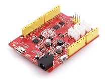
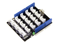
| Seeeduino V4.2 | Base Shield | Grove - Red LED |
|---|---|---|
|
|
|
| Get ONE Now | Get ONE Now | Get ONE Now |
- Step 2. Connect Grove-Red LED to port D2 of Grove-Base Shield.
- Step 3. Plug Grove - Base Shield into Seeeduino.
- Step 4. Connect Seeeduino to PC through a USB cable.

If we don't have Grove Base Shield, We also can directly connect Grove-Red_Led to Seeeduino as below.
| Seeeduino | Grove-Red Led |
|---|---|
| 5V | Red |
| GND | Black |
| Not Conencted | White |
| D2 | Yellow |
Software
- Step 1. Copy the code into Arduino IDE and upload.
void setup() {
  // initialize digital pin2  as an output.
  pinMode(2, OUTPUT);
}

// the loop function runs over and over again forever
void loop() {
  digitalWrite(2, HIGH);   // turn the LED on (HIGH is the voltage level)
  delay(1000);                       // wait for a second
  digitalWrite(2, LOW);    // turn the LED off by making the voltage LOW
  delay(1000);                       // wait for a second
}
- Step 2. We will see the LED on and off.
Play with Codecraft
Hardware
Step 1. Connect Grove - Red LED to port D2 of a Base Shield.
Step 2. Plug the Base Shield to your Seeeduino/Arduino.
Step 3. Link Seeeduino/Arduino to your PC via an USB cable.
Software
Step 1. Open Codecraft, add Arduino support, and drag a main procedure to working area.
If this is your first time using Codecraft, see also [Guide for Codecraft using Arduino](https://wiki.seeedstudio.com/Guide_for_Codecraft_using_Arduino/).
Step 2. Drag blocks as picture below or open the cdc file which can be downloaded at the end of this page.

Upload the program to your Arduino/Seeeduino.
When the code finishes uploaded, you will see the LED blinking.
Play With Raspberry Pi (With Grove Base Hat for Raspberry Pi)
Hardware
- Step 1. Things used in this project:
| Raspberry pi | Grove Base Hat for RasPi | Grove - Red LED |
|---|---|---|
|
|
|
| Get ONE Now | Get ONE Now | Get ONE Now |
- Step 2. Plug the Grove Base Hat into Raspberry.
- Step 3. Connect the Red LED to port 12 of the Base Hat.
- Step 4. Connect the Raspberry Pi to PC through USB cable.

For step 3 you are able to connect the Red LED to **any GPIO Port** but make sure you change the command with the corresponding port number.
Software
If you are using **Raspberry Pi with Raspberrypi OS >= Bullseye**, you have to use this command line **only with Python3**.
- Step 1. Follow Setting Software to configure the development environment.
- Step 2. Download the source file by cloning the grove.py library.
cd ~
git clone https://github.com/Seeed-Studio/grove.py
- Step 3. Excute below command to run the code.
cd yourpath/grove.py/grove
python3 grove_led.py 12
If you connect the Red LED to the different port of the Base Hat, instead of excuting python grove_led.py 12, you should run the following command.
python3 grove_led.py portnumber
Following is the grove_led.py code.
from grove.gpio import GPIO


class GroveLed(GPIO):
    def __init__(self, pin):
        super(GroveLed, self).__init__(pin, GPIO.OUT)

    def on(self):
        self.write(1)

    def off(self):
        self.write(0)


Grove = GroveLed


def main():
    import sys
    import time

    if len(sys.argv) < 2:
        print('Usage: {} pin'.format(sys.argv[0]))
        sys.exit(1)

    led = GroveLed(int(sys.argv[1]))

    while True:
        led.on()
        time.sleep(1)
        led.off()
        time.sleep(1)


if __name__ == '__main__':
    main()
If everything goes well, you will be able to see the led on and off.
For most of the grove modules, you need to add the pin number parameter, as in this example `python3 grove_led.py 12`, **12** is the chosen GPIO pin and the output from pin 12 will feed the led.
Play With Raspberry Pi (with GrovePi_Plus)
Hardware
- Step 1. Prepare the below stuffs:
| Raspberry pi | GrovePi_Plus | Grove - Red Led |
|---|---|---|
|
|
|
| Get ONE Now | Get ONE Now | Get ONE Now |
- Step 2. Plug the GrovePi_Plus into Raspberry.
- Step 3. Connect Grove-Red Led to D4 port of GrovePi_Plus.
- Step 4. Connect the Raspberry to PC through USB cable.

Software
If you are using **Raspberry Pi with Raspberrypi OS >= Bullseye**, you have to use this command line **only with Python3**.
- Step 1. Follow Setting Software to configure the development environment.
- Step 2. Git clone the Github repository.
cd ~
git clone https://github.com/DexterInd/GrovePi.git
- Step 3. Excute below commands.
cd ~/GrovePi/Software/Python
python3 grove_led_blink.py
Here is the grove_led_blink.py code.
import time
from grovepi import *

# Connect the Grove LED to digital port D4
led = 4

pinMode(led,"OUTPUT")
time.sleep(1)

print ("This example will blink a Grove LED connected to the GrovePi+ on the port labeled D4. If you're having trouble seeing the LED blink, be sure to check the LED connection and the port number. You may also try reversing the direction of the LED on the sensor.")
print (" ")
print ("Connect the LED to the port labele D4!" )

while True:
    try:
        #Blink the LED
        digitalWrite(led,1)     # Send HIGH to switch on LED
        print ("LED ON!")
        time.sleep(1)

        digitalWrite(led,0)     # Send LOW to switch off LED
        print ("LED OFF!")
        time.sleep(1)

    except KeyboardInterrupt:   # Turn LED off before stopping
        digitalWrite(led,0)
        break
    except IOError:             # Print "Error" if communication error encountered
        print ("Error")
- Step 4. We will see the led on and off.
pi@raspberrypi:~/GrovePi/Software/Python $ python3 grove_led_blink.py
This example will blink a Grove LED connected to the GrovePi+ on the port labeled D4.
If you're having trouble seeing the LED blink, be sure to check the LED connection and the port number.
You may also try reversing the direction of the LED on the sensor.

Connect the LED to the port labele D4!
LED ON!
LED OFF!
LED ON!
LED OFF!
Resources
- [PDF] Grove-Red LED Schematic
- [Codecraft] CDC File
Projects
Using Grove Button To Control Grove LED: How to connect and use Grove Button to control Grove LED socket kit.
Button and LED Grove modules:
Tech Support
Please do not hesitate to submit the issue into our forum.


