Grove - Red LED Matrix w/Driver

LED Matrix is low cost and usually used to display simple numbers and images. Grove - Red LED Matrix w/Driver is the combination of the 20mm 8*8 square LED Matrix - Red and the Grove - LED Matrix Driver. The HT16K33 is a memory mapping and multi-function LED controller driver which allows you to control the LED matrix with our prepared and easy-to-use libraries, or you can create your own library to control it to satisfy your need.
Version
| Product Version | Changes | Released Date |
|---|---|---|
| Grove - Red LED Matrix w/Driver | Initial | Sep 2018 |
Feature
- Integrated RC oscillator
- R/W address auto increment
- Max. 8 x 8 patterns
- I^2^C-bus interface
##Specification
| Item | Value |
|---|---|
| Supply Voltage | 3.3V / 5V |
| LED Matrix Dot NO. | 8 * 8 |
| Operating temperature | -40~85℃ |
| Storage temperature | -50~125℃ |
| Interface | I2C |
| I2C address | 0x70(defult) 0x71~0x77(configurable) |
| Size | L: 40mm W: 40mm H: 21mm |
| Weight | 17.4g |
| Package size | L: 140mm W: 90mm H: 20mm |
| Gross Weight | 24g |
There are 8 possible I2C address of this grove, from 0x70 to 0x77. The defult I^2^C address is 0x77. You can change the I2C address by do some soldering as instructed in the below table.
| I^2^C address | Connection |
|---|---|
| 0x70 | Disconnect: A0 A1 A2 |
| 0x71 | Disconnect: A1 A2, Connect: A0 |
| 0x72 | Disconnect: A0 A2, Connect: A1 |
| 0x73 | Disconnect: A2, Connect: A1 A0 |
| 0x74 | Disconnect: A0 A1, Connect: A2 |
| 0x75 | Disconnect: A1, Connect: A0 A2 |
| 0x76 | Disconnect: A0, Connect: A1 A2 |
| 0x77 | Connect: A0 A1 A2 |
For example, if I want to change the address to 0x73, I need to connect pad A1,A0 and disconnect pad A2. Then I will get address 0b01110011, that is 0x73.

Typical applications
- Industrial control indicators
- Digital clocks, thermometers, counters, multimeters
- Combo sets
- VCR sets
- Instrumentation readouts
- Other consumer applications
- LED Displays
Hardware Overview
Pin Out

Platforms Supported
| Arduino | Raspberry Pi |
|---|---|
|
|
Getting Started
Play With Arduino
Materials required
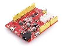
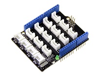
| Seeeduino V4.2 | Base Shield | Grove - Red LED Matrix w/Driver |
|---|---|---|
|
|
|
| Get ONE Now | Get ONE Now | Get ONE Now |
**1.** Please plug the USB cable gently, otherwise you may damage the port. Please use the USB cable with 4 wires inside, the 2 wires cable can't transfer data. If you are not sure about the wire you have, you can click [here](https://www.seeedstudio.com/Micro-USB-Cable-48cm-p-1475.html) to buy

**2.** Each Grove module comes with a Grove cable when you buy. In case you lose the Grove cable, you can click [here](https://www.seeedstudio.com/Grove-Universal-4-Pin-Buckled-20cm-Cable-%285-PCs-pack%29-p-936.html) to buy.
Step 1. Connect the Grove - Red LED Matrix w/Driver to port I^2^C of Grove-Base Shield.
Step 2. Plug Grove - Base Shield into Seeeduino.
Step 3. Connect Seeeduino to PC via a USB cable.

Software
If this is the first time you work with Arduino, we strongly recommend you to see [Getting Started with Arduino](https://wiki.seeedstudio.com/Getting_Started_with_Arduino/) before the start.
Step 1. Download the Grove_LED_Matrix_Driver_HT16K33 Library from Github.
Step 2. Refer to How to install library to install library for Arduino.
Step 3. Restart the Arduino IDE. Open the example, you can open it in the following three ways:
Open it directly in the Arduino IDE via the path: File --> Examples -->Grove - LED Matrix Driver(HT16K33 with 8*8 LED Matrix) --> display_bars.

Open it in your computer by click the basic_demo.ino which you can find in the folder XXXX\Arduino\libraries\Grove_LED_Matrix_Driver_HT16K33\examples\display_bars\display_bars.ino, XXXX is the location you installed the Arduino IDE.

Or, you can just click the icon

in upper right corner of the code block to copy the following code into a new sketch in the Arduino IDE.
#include <Wire.h>
#include "Grove_LED_Matrix_Driver_HT16K33.h"


Matrix_8x8 matrix;

void setup()
{
    Wire.begin();
    matrix.init();
    matrix.setBrightness(0);
    matrix.setBlinkRate(BLINK_OFF);
}

void loop()
{
    for (int i=0;i<33;i++)
    {
        // The input range of writeBar is [0-32]
        matrix.writeBar(i);
        matrix.display();
        delay(150);
    }
}
The library file may be updated. This code may not be applicable to the updated library file, so we recommend that you use the first two methods.
If everything goes well, you will be able to see various bars display on the LED matrix.
If you would like to run other examples, you may do similar processes and be able to see different displays.
DIY
Are you willing to let the LED matrix to display the emoji? Now, it is your turn to design your own. Prepare yourself with the above-listed Hardware and Software requirements.
Step 1. Use the online LED Matrix Editor to edit and create animations for 8*8 LED matrices.
Step 2. Select the LEDs color on the top right corner. In my case, I choose 'red' as I am using the Red LED Matrix.
Step 3. Create your own design by simply click on the blank dot.
Step 4. Copy the hex file generated according to your design. There are two ways you can do this:
- copy the hex value in the hex box at the bottom left corner.
- copy the corresponding code in the Arduino/C code section.

- Step 5. Create the new '.ino' file under the same folder with other LED Matrix examples and copy below code.
#include "Grove_LED_Matrix_Driver_HT16K33.h"
#include <Wire.h>

//put your own design hex group here.
const uint64_t Emoji[] =
{
  0x3c4299a581a5423c,
  0x3c4281bd81a5423c,
  0x3c42a59981a5423c,
};

Matrix_8x8 matrix;


void setup() {
    Wire.begin();
    matrix.init();
    matrix.setBrightness(0);
    matrix.setBlinkRate(BLINK_OFF);
    /*************************************************************
    * Description
    *    Setting the blink rate of matrix
    * Parameter
    *    blink_type: BLINK_OFF, BLINK_2HZ, BLINK_1HZ
    * Return
    *    Null.
    *************************************************************/
}

void loop() {
  for (int i = 0;i < 3;i++)
    {
        matrix.writeOnePicture(Emoji[i]);
        /*************************************************************
        * Description
        *    Write a picture in display buffer.
        *    Call display() to show display buffer.
        * Parameter
        *    pic: A uint64_t type 8x8 matrix picture, you can make it at
        *         https://xantorohara.github.io/led-matrix-editor/#
        * Return
        *    Null.
        *************************************************************/
        matrix.display();
        /*************************************************************
        * Description
        *    Clear the display buffer.
        *    This function will display nothing on 8x8 Matrix after call display().
        * Parameter
        *    Null.
        * Return
        *    Null.
        *************************************************************/
        delay(500);
    }
}
- Step 6. Upload your project to your seeeduino.
If everything goes well, your LED Matrix will display as below.

Schematic Online Viewer
Resources
[PDF] Datasheet HT16K33
Tech Support
Please do not hesitate to submit the issue into our forum.


