Grove-Doppler-Radar

How would you build a system that could calculate the distance towards an object or detect whether there is motion present? Normally you would use an Ultrasonic or LiDAR Sensor for distance measurement and PIR Motion Sensor for motion detection. What if we told you there is an all-in-one module that could do all these functions more precisely and also perform functions such as velocity detection of moving objects and angle detection of objects. Would you believe it? We were tired of using these traditional modules for motion-sensing applications and wanted to deliver you a better solution, integrating new technologies. Well…For the first time in the history of Grove, we are very excited to bring you a Grove Module based on Radar Technology!
This is the Grove – Doppler Radar.
The Grove – Doppler Radar is based on the BGT24LTR11 Silicon Germanium MMIC which is a 24GHz radar transceiver. It is driven by an XMC1302 MCU based on Arm® Cortex®-M0. This comes in a compact package and runs on very low power, providing high-precision measurements.The high frequency of this module allows for high penetration though objects and therefore this module does not need to be exposed outside when deploying, but rather behind an object. This, in turn, is extremely useful in security systems. Also, this is able to operate in harsh weather conditions such as high temperatures, dust, and rain.
Feature
- The first radar-based sensor in the Grove Family
- Compact size for easy deployment
- Light-weight design, suitable for UAV applications
- Low power consumption for prolonged usage
- 24GHz Transceiver MMIC for high-precision measurements
- Fast response using electromagnetic waves
- ESD protection to avoid system failures caused by ESD strikes
- High penetration which allows it to be deployed behind an object
- Maintains operation through harsh weather conditions (temperature, light, dust, rain)
Specification
| Item | Value |
|---|---|
| MMIC | BGT24LTR11 |
| MCU | XMC1302 Arm® Cortex®-M0 |
| Transmission Frequency | Min: 24GHz |
| Typical | 21.125GHz |
| Max | 24.25GHz |
| Output Power (EIRP) | 7dBm @ 25°C |
| Update Time | 300ms |
| Communication Interface | UART (115200) |
| Detection Distance | 10m @ 0dBsm |
| Standard Detection Field | 65° / horizontal (-6dB); 22° / vertical (-6dB) |
| Supply Voltage | 3.3-5V |
| Weight | 5g |
Applications
- Smart Home
- Smart Building
- Automatic Door
- Lighting Control
- Industrial Robotics
- Intruder Alarm Systems
- UAV
How Does Doppler Radar Technology Work in This Module?
Doppler radar works by sending a beam of electromagnetic radiation waves from the transmitter (TX Antenna), with a precise frequency, at a moving object. Once the electromagnetic radiation wave comes in contact with an object, it travels back towards the receiver (RX Antenna). However, when the wave got reflected from the moving object, the wave now has a different frequency compared to the original frequency, it emitted. Then the change in this frequency can be used to calculate the velocity of the moving object.

Platform Supported
| Arduino | Raspberry Pi | |||
|---|---|---|---|---|
 |  |  |  |  |
Getting Started
Materials Requied
| Seeeduino XIAO | Grove-Doppler-Radar | XIAO Expansion Board |
|---|---|---|
 |  |  |
| Get ONE Now | Get ONE Now | Coming SOON |
Hardware Overview

External headers-pin description
| Pin number | Signal name | Pin description |
|---|---|---|
| 1 | DIV_OUT | Frequency divider output from the BGT24LTR11 |
| 2 | GND | Ground |
| 3 | VCC_5V_EXT | External+5.0V input power supply pin(maximum=5.5V) |
| 4 | VTUNE | VCO frequency tuning voltage |
| 5 | IFQ_HG | BGT24LTR11 Q-channel-analog signal output-second gain stage |
| 6 | IFI_HG | BGT24LTR11 I-channel-analog signal output-second gain stage |
| 7 | PWM_OUT | External user-configurable GPIO with CCU4 |
| 8 | OUT1 | External GPIO pin (user configurable) |
| 9 | OUT2 | External GPIO pin (user configurable) |
Hardware Connection

Please plug the USB cable, Doppler Radar Interface into Seeeduino XIAO expansion board Interface gently, otherwise you may damage the port.
Step 1. Plug Doppler Radar into Seeeduino XIAO expansion board with a Grove Cable.
Step 2. Connect Seeeduino XIAO to PC via a USB cable.
Step 3. Download the code, please refer to the software part.
Step 4. Run the code and the outcome will display on the screen of Serial Monitor in your Arduino IDE .
Software
If this is the first time you work with Arduino, we strongly recommend you to see [Getting Started with Arduino](https://wiki.seeedstudio.com/Getting_Started_with_Arduino/) before the start.
Step 1. Download the Demo code.
Step 2. Copy the whole Seeed_Arduino_DopplerRadar file and paste it into your Arduino IDE library file.
Step 3. Open the BGT24LTR11_DETECTION_TARGET file with your Arduino IDE.
Step 4. Upload the demo. If you do not know how to upload the code, please check How to upload code.
Software Code
#include "GBT24LTR11.h"

#ifdef __AVR__
    #include <SoftwareSerial.h>
    SoftwareSerial SSerial(2, 3); // RX, TX
    #define COMSerial SSerial
    #define ShowSerial Serial

    GBT24LTR11<SoftwareSerial> GBT;
#endif

#ifdef ARDUINO_SAMD_VARIANT_COMPLIANCE
    #define COMSerial Serial1
    #define ShowSerial SerialUSB

    GBT24LTR11<Uart> GBT;
#endif

#ifdef ARDUINO_ARCH_STM32F4
    #define COMSerial Serial
    #define ShowSerial SerialUSB

    GBT24LTR11<HardwareSerial> GBT;
#endif

void setup() {
    // put your setup code here, to run once:
    ShowSerial.begin(9600);
    COMSerial.begin(115200);
    GBT.init(COMSerial);
    while (!ShowSerial)
        ;
    while (!COMSerial)
        ;
    /*
        MODE 0 -->detection target mode
        MODE 1 -->I/Q ADC mode
    */
    while (!GBT.setMode(0))
        ;
}

void loop() {
    // put your main code here, to run repeatedly:
    uint16_t state = 0;
    ShowSerial.print("target speed:");
    ShowSerial.println(GBT.getSpeed());
    state = GBT.getTargetState();
    //2 --> target approach
    //1 --> target leave
    //0 --> Not Found target
    if (state == 2) {
        ShowSerial.println("target approach");
    } else if (state == 1) {
        ShowSerial.println("target leave");
    }
    delay(200);
}
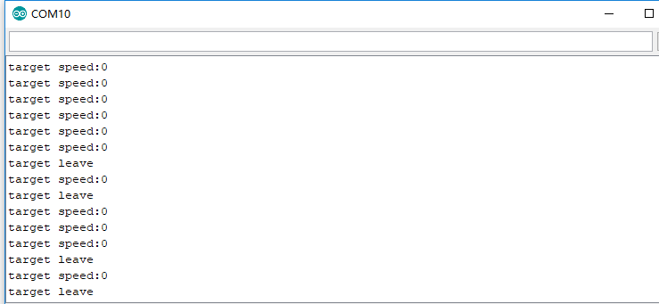
If everything goes well, you can go to **Serial Monitor** to see an outcome as following:

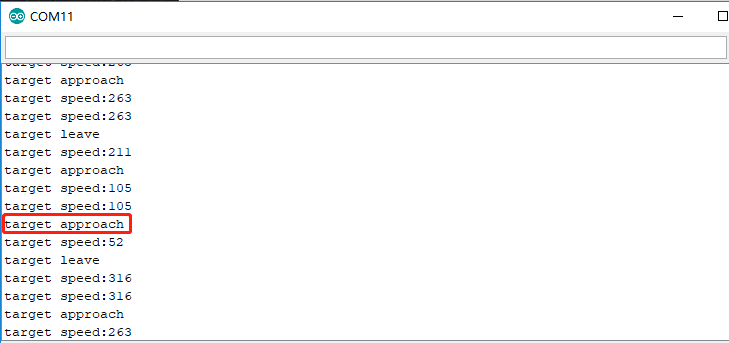
And if there's an object approaching the radar or passing by, the outcome will alter as below:

The minimum speed accuracy that the sensor is capable of detecting is 52cm/s, which equals to 0.52m/s, 3.6km/h and 2.23mph. Additionally, the results returned by function getSpeed() are multiples of 52cm/s and are absolute values accordingly.
Resources
- [ZIP] Demo Code library
- [PDF] Grove_DopplerRadar(BGT24LTR11)Radar_module_communication_protocol_v1.1.pdf
Tech Support
if you have any technical issue. submit the issue into our forum.

