Grove - Optocoupler Relay (M281)

This module is a bi-directional SPSD(single-pole, single-throw), normally open solid state relay(SSR). The Grove Optocoupler Relay (M281) offers very low on-resistance, which allowing a high load current rating.
Unlike the other TRIAC SSR in our website, this relay is based on MOSFET, so it can carry both AC load and DC load. If you need to use a SSR with the DC load, this is what you want!
Version
| Product Version | Changes | Released Date |
|---|---|---|
| Grove-Optocoupler Relay (M281) | Initial | Dec 2018 |
Features
- Low on-resistance(0.5Ω MAX.)
- 1A continuous load current
- 60V load voltage rating
- Low input control current(3mA TYP.)
- High input-to-output isolation(1.5kV MIN.)
Applications
- Automated Test Equipment
- Meter reading systems
- Medical equipment
- Battery monitoring
- Multiplexers
Specification
| Parameter | Value |
|---|---|
| Supply voltage | 3.3V / 5V |
| Operating temperature | -40 – 85℃ |
| Storage temperature | - 55°C – 125°C |
| Blocking voltage | 60 V |
| Continuous load current | 1A |
| Leakage current | 0.2 uA(TYP.) 1 uA(Max.) |
| On-Resistance | 0.5 Ω(TYP.) 0.7 Ω(Max.) |
| Isolation resistance | 100 GΩ |
| Turn-On time | 1.4 ms(TYP.) 5 ms(Max.) |
| Turn-Off time | 0.2 ms(TYP.) 2 ms(Max.) |
| Interface | Digital |
| Size | L: 40mm W: 20mm H: 13mm |
| Weight | 10.6g |
| Package Size | L: 135mm W: 85mm H: 13mm |
| Gross Weight | 11g |
Hardware Overview
Pinout
Platforms Supported
| Arduino | Raspberry Pi | |||
|---|---|---|---|---|
 |  |  |  |  |
Getting Started
Play With Arduino
Hardware
Materials required
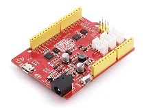
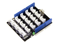
| Seeeduino V4.2 | Base Shield | Grove - Optocoupler Relay (M281) | Red LED |
|---|---|---|---|
 |  |  |  |
| Get ONE Now | Get ONE Now | Get ONE Now | Get ONE Now |
In addition, you can consider our new Seeeduino Lotus M0+, which is equivalent to the combination of Seeeduino V4.2 and Baseshield.
**1** Please plug the USB cable gently, otherwise you may damage the port. Please use the USB cable with 4 wires inside, the 2 wires cable can't transfer data. If you are not sure about the wire you have, you can click [here](https://www.seeedstudio.com/Micro-USB-Cable-48cm-p-1475.html) to buy

**2** Each Grove module comes with a Grove cable when you buy. In case you lose the Grove cable, you can click [here](https://www.seeedstudio.com/Grove-Universal-4-Pin-Buckled-20cm-Cable-%285-PCs-pack%29-p-936.html) to buy.
Hardware Connection
Step 1. Plug Grove - Base Shield into Seeeduino.
Step 2. Connect the Grove - Optocoupler Relay (M281) to the D5 port of the Base Shield.
Step 3. Connect the LED and the Grove - Optocoupler Relay (M281) to the 3.3V and GND pin of the Grove - Base Shield.(Please refer to the figure below)
Step 4. Connect Seeeduino to PC via a USB cable.
Software
If this is the first time you work with Arduino, we strongly recommend you to see [Getting Started with Arduino](https://wiki.seeedstudio.com/Getting_Started_with_Arduino/) before the start.
- Step 1. Copy the following code into a new sketch in the Arduino IDE
const int Pinout = 5;

void setup() {
 pinMode(Pinout, OUTPUT);
 Serial.begin(9600);
}

void loop() {

  digitalWrite(Pinout, HIGH);
  delay(500);
  digitalWrite(Pinout, LOW);
  delay(500);
}
- Step 2. Upload the demo. If you do not know how to upload the code, please check How to upload code.
If everything goes well, we will see the LED flashing.
Schematic Online Viewer
Resources
Tech Support
if you have any technical issue. submit the issue into our forum.


