Gear Stepper Motor Driver Pack

The Gear Stepper Motor Driver Pack includes a stepper motor and a motor drive board. It's a four-phase eight-stepping stepper motor, and you can easily control this stepper motor via the drive board.
You can use this pack for position control.
Features
- Low noise
- Large torque
- Built-in gearbox
Specification
| Item | Value |
|---|---|
| Operating Voltage | 5V |
| Phase | 4 |
| Reduction ratio | 1/64 |
| Step Angle | 5.625°/64 |
| Diameter | 28mm / Nema 11 |
| Idle In-traction Frequency | >500HZ |
| Idle Out-traction Frequency | >1000HZ |
| Resistance | 21±7% |
| Noise | ≤40dB |
| Drive mode | four-phase eight-stepping |
Typical applications
- Desktop printers
- Plotters
- 3d printers
- CNC milling machines
Hardware Overview
Pin Out


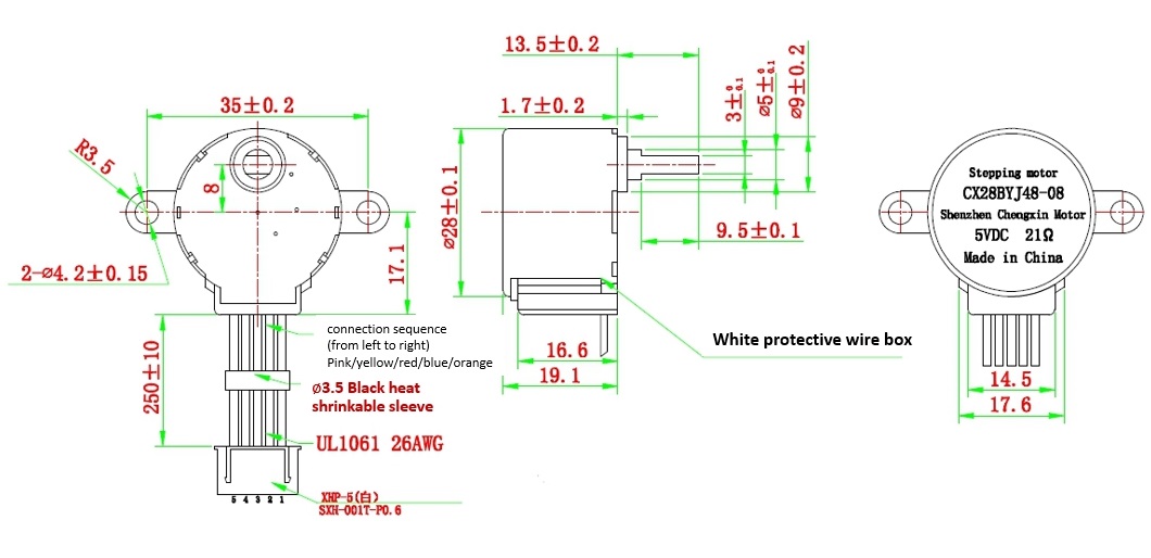
Mechanical drawing
you can click it to see the original picture.
Platforms Supported
| Arduino | Raspberry Pi | |||
|---|---|---|---|---|
 |  |  |  |  |
tip
The platforms mentioned above as supported is/are an indication of the module's software or theoritical compatibility. We only provide software library or code examples for Arduino platform in most cases. It is not possible to provide software library / demo code for all possible MCU platforms. Hence, users have to write their own software library.
Getting Started
Play With Arduino
Hardware
Materials required
| Seeeduino V4.2 | Gear Stepper Motor Driver Pack | Female-Male jumpers |
|---|---|---|
 |  |  |
| Get One Now | Get One Now | Get One Now |
note
**1** Please plug the USB cable gently, otherwise you may damage the port. Please use the USB cable with 4 wires inside, the 2 wires cable can't transfer data. If you are not sure about the wire you have, you can click [here](https://www.seeedstudio.com/Micro-USB-Cable-48cm-p-1475.html) to buy

**2** To make the Gear-Stepper-Motor-Driver-Pack work with your Arduino, several Female-Male jumpers is also required. In case you do not have jumpers, you can click [here](https://www.seeedstudio.com/1-Pin-Female-Male-Jumper-Wire-125mm-50pcs-pac-p-1319.html) to buy.
- Step 1. Connect the Gear Stepper Motor Driver Board to your seeedunio via jumppers.
| Seeeduino | Gear Stepper Motor Driver Board |
|---|---|
| Digital Pin 8 | IN1 |
| Digital Pin 9 | IN2 |
| Digital Pin 10 | IN3 |
| Digital Pin 11 | IN4 |
| GND | GND |
| VCC_5V | VCC |
| VCC_5V | VM |
tip
You can connect the VM pin to VCC_5V or you can just do not use it as long as you choose the VCC in the switch.
Step 2. Plug the stepper motor into the Gear Stepper Motor Driver Board.
Step 3. Connect Seeeduino to PC via a USB cable.

Software
note
If this is the first time you work with Arduino, we strongly recommend you to see [Getting Started with Arduino](https://wiki.seeedstudio.com/Getting_Started_with_Arduino/) before the start.
- Step 1. Click the icon
 in upper right corner of the code block to copy the following code into a new sketch in the Arduino IDE.
int pwm1=9;
int pwm2=10;
int ctr_a =9;
int ctr_b =8;
int ctr_c =11;
int ctr_d =10;
int sd =6;
int i=0;
int t=1500;

void setup()
{
    //pinMode(sd,OUTPUT);
    //pinMode(pwm1,OUTPUT);
    //pinMode(pwm2,OUTPUT);
    pinMode(ctr_a,OUTPUT);
    pinMode(ctr_b,OUTPUT);
    pinMode(ctr_c,OUTPUT);
    pinMode(ctr_d,OUTPUT);
    delay(1);
    //digitalWrite(sd,HIGH);
    //digitalWrite(pwm1,HIGH);
    //digitalWrite(pwm2,HIGH);
//    digitalWrite(ctr_a,LOW);
//    digitalWrite(ctr_b,LOW);
//    digitalWrite(ctr_c,LOW);
//    digitalWrite(ctr_d,LOW);

}


void loop ()
{
//   for(i=1500;i>=1;i--)
//   {
//       digitalWrite(ctr_a,HIGH);//A
//       digitalWrite(ctr_b,LOW);
//       digitalWrite(ctr_c,LOW);
//       digitalWrite(ctr_d,LOW);
//       delay(t);
//       digitalWrite(ctr_a,HIGH);
//       digitalWrite(ctr_b,HIGH);//AB
//       digitalWrite(ctr_c,LOW);
//       digitalWrite(ctr_d,LOW);
//       delay(t);
//       digitalWrite(ctr_a,LOW);
//       digitalWrite(ctr_b,HIGH);//B
//       digitalWrite(ctr_c,LOW);
//       digitalWrite(ctr_d,LOW);
//       delay(t);
//       digitalWrite(ctr_a,LOW);
//       digitalWrite(ctr_b,HIGH);
//       digitalWrite(ctr_c,HIGH);//BC
//        digitalWrite(ctr_d,LOW);
//       delay(t);
//       digitalWrite(ctr_a,LOW);
//       digitalWrite(ctr_b,LOW);
//       digitalWrite(ctr_c,HIGH);//C
//       digitalWrite(ctr_d,LOW);
//       delay(t);
//       digitalWrite(ctr_a,LOW);
//       digitalWrite(ctr_b,LOW);
//       digitalWrite(ctr_c,HIGH);//CD
//       digitalWrite(ctr_d,HIGH);
//       delay(t);
//        digitalWrite(ctr_a,LOW);
//       digitalWrite(ctr_b,LOW);
//       digitalWrite(ctr_c,LOW);//D
//       digitalWrite(ctr_d,HIGH);
//       delay(t);
//        digitalWrite(ctr_a,HIGH);
//       digitalWrite(ctr_b,LOW);
//       digitalWrite(ctr_c,LOW);//DA
//       digitalWrite(ctr_d,HIGH);
//       delay(t);
//
//   }
//       digitalWrite(ctr_a,LOW);
//       digitalWrite(ctr_b,LOW);
//       digitalWrite(ctr_c,LOW);
//       digitalWrite(ctr_d,LOW);
//
//
//
//     for(i=1500;i>=1;i--)
//   {
//
//       digitalWrite(ctr_d,HIGH);//D
//       delay(t);
//       digitalWrite(ctr_c,HIGH);//DC
//       delay(t);
//       digitalWrite(ctr_d,LOW);//C
//       delay(t);
//       digitalWrite(ctr_b,HIGH);//CB
//       delay(t);
//       digitalWrite(ctr_c,LOW);//B
//       delay(t);
//       digitalWrite(ctr_a,HIGH);//BA
//       delay(t);
//       digitalWrite(ctr_b,LOW);//A
//       delay(t);
//       digitalWrite(ctr_d,HIGH);//AD
//       delay(t);
//       digitalWrite(ctr_a,LOW);
//       digitalWrite(ctr_d,LOW);
//   }

   for(i=1500;i>=1;i--)
   {
       digitalWrite(ctr_a,LOW);//A
       digitalWrite(ctr_b,HIGH);
       digitalWrite(ctr_c,HIGH);
       digitalWrite(ctr_d,HIGH);
       delayMicroseconds(t);
       digitalWrite(ctr_a,LOW);
       digitalWrite(ctr_b,LOW);//AB
       digitalWrite(ctr_c,HIGH);
       digitalWrite(ctr_d,HIGH);
       delayMicroseconds(t);
       digitalWrite(ctr_a,HIGH);
       digitalWrite(ctr_b,LOW);//B
       digitalWrite(ctr_c,HIGH);
       digitalWrite(ctr_d,HIGH);
       delayMicroseconds(t);
       digitalWrite(ctr_a,HIGH);
       digitalWrite(ctr_b,LOW);
       digitalWrite(ctr_c,LOW);//BC
        digitalWrite(ctr_d,HIGH);
       delayMicroseconds(t);
       digitalWrite(ctr_a,HIGH);
       digitalWrite(ctr_b,HIGH);
       digitalWrite(ctr_c,LOW);//C
       digitalWrite(ctr_d,HIGH);
       delayMicroseconds(t);
       digitalWrite(ctr_a,HIGH);
       digitalWrite(ctr_b,HIGH);
       digitalWrite(ctr_c,LOW);//CD
       digitalWrite(ctr_d,LOW);
       delayMicroseconds(t);
        digitalWrite(ctr_a,HIGH);
       digitalWrite(ctr_b,HIGH);
       digitalWrite(ctr_c,HIGH);//D
       digitalWrite(ctr_d,LOW);
       delayMicroseconds(t);
       digitalWrite(ctr_a,LOW);
       digitalWrite(ctr_b,HIGH);
       digitalWrite(ctr_c,HIGH);//DA
       digitalWrite(ctr_d,LOW);
       delayMicroseconds(t);

   }
//       digitalWrite(ctr_a,HIGH);
//       digitalWrite(ctr_b,HIGH);
//       digitalWrite(ctr_c,HIGH);
//       digitalWrite(ctr_d,HIGH);
//


//     for(i=1500;i>=1;i--)
//   {
//
//       digitalWrite(ctr_d,HIGH);//D
//       delay(t);
//       digitalWrite(ctr_c,HIGH);//DC
//       delay(t);
//       digitalWrite(ctr_d,LOW);//C
//       delay(t);
//       digitalWrite(ctr_b,HIGH);//CB
//       delay(t);
//       digitalWrite(ctr_c,LOW);//B
//       delay(t);
//       digitalWrite(ctr_a,HIGH);//BA
//       delay(t);
//       digitalWrite(ctr_b,LOW);//A
//       delay(t);
//       digitalWrite(ctr_d,HIGH);//AD
//       delay(t);
//       digitalWrite(ctr_a,LOW);
//       digitalWrite(ctr_d,LOW);
//   }


}
- Step 2. Upload the demo. If you do not know how to upload the code, please check How to upload code.
tip
If every thing goes well, you can see the motor run:

Resources
Tech Support
if you have any technical issue. submit the issue into our forum.


