Build LoRaWAN Sensors with SenseCAP S2110 Grove to MODBUS RS485 Converter and SenseCAP Data Logger
SenseCAP S2110 Grove to MODBUS RS485 Converter is an open-source tool to build RS485 sensors with 500+ Grove sensors. It also enables developers to build a custom industrial-grade LoRaWAN sensor connecting to SenseCAP Cloud with SenseCAP Data Logger.
Note: From here on, we will refer SenseCAP S2110 Grove to MODBUS RS485 Converter as SenseCAP S2110 Converter for convenience

It has Seeed Studio XIAO RP2040 as the dual-core ARM Cortex M0+ processor, and has one Grove and one RS485 connector, enabling developers to connect with 500+ Grove sensors and various MODBUS RS485 sensors to develop custom industrial-grade MODBUS RS485 sensors for various IoT applications.

For the LoRaWAN application, developers could easily connect it with a SenseCAP LoRaWAN Data Logger(*Grove sensors and data logger are not included in the product, learn more on the bundle kit here) to transfer the data to SenseCAP Cloud, which only takes a 5-minute simple BLE configuration in SenseCAP Mate App. Clear data results and further analysis could be easily obtained from SenseCAP Dashboard and SenseCAP Mate App. IoT platforms such as Helium, TTN, LORIOT, etc. are also supported.

The product comes with an IP66 industrial-grade enclosure and also the mounting pads and screws set, which enables you to deploy the sensor outdoors easily and safely.


Features
- Easily build Modbus RS485 Industrial-grade Sensors: With open-source source code and IP66 enclosure, easily convert over 500+ existing Grove sensors to Modbus RS485 industrial-grade sensors. 6 of the most popular environmental Grove sensors are already fully compatible with native firmware with more to come
- SenseCAP Data Logger and IoT Platform Compatible: Convert to a SenseCAP LoRaWAN® sensor with SenseCAP Data Logger and take advantage of quick and easy set-up in just 5-minutes with SenseCAP Mate APP
- Supports Third-party Data Loggers and IoT Platforms: Besides SenseCAP Data Logger, developers could connect to other data loggers that support Modbus RS485 protocol and third-party IoT platforms
- Ready-to-deploy Industrial-grade Outdoor Enclosure: IP66 waterproof rate outdoor enclosure with window and waterproof ventilation hole reserved for light and gas sensors, also comes with a customized mounting panel, suitable for pole and wall installation
- Powered by Seeed Studio XIAO RP2040: Take advantage of the powerful Seeed Studio XIAO RP2040 dual-core ARM M0+ processor and vast open-source resources to customize your own sensor. Easily upload code via USB-C port
Get Started
Preparation
1.LoRaWAN network coverage
Check whether you are within LoRaWAN network coverage of Helium or TTN (The Things Network). If you do not have coverage, you can use any gateway powered by Helium/ TTN to send the sensor data to the cloud. However, this wiki focuses on sending the sensor data to Sensecap platform. And to do that, you need to have either a SenseCAP Outdoor LoRaWAN Gateway for TTN or SenseCAP M1 LoRaWAN Indoor Gateway or SenseCAP M2 LoRaWAN Indoor Gateway or any other Helium-enabled gateway for Helium.
2.SenseCAP S2110 Converter x 1
3.SenseCAP Data Logger x 1
4.Grove Sensor x 1
Currently, SenseCAP S2110 Converter supports the following Grove modules out-of-the-box to communicate with SenseCAP Data Logger and send the sensor data to the SenseCAP platform via LoRa.
- Grove - Temperature and Barometer Sensor (BMP280)
- Grove - Oxygen Sensor (MIX8410)
- Grove - CO2 & Temperature & Humidity Sensor - SCD41
- Grove - Sunlight Sensor - SI1151
- Grove - Light Sensor v1.2 - LS06-S phototransistor
- Grove - Flame Sensor
We will add support to more Grove sensors in the near future. So stay tuned! We have made the source code for SenseCAP S2110 Converter open-source so that users could develop their own Grove sensors as well!
Connect Grove Sensor to SenseCAP S2110 Grove to MODBUS RS485 Converter
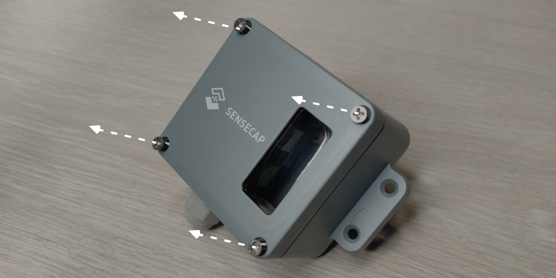
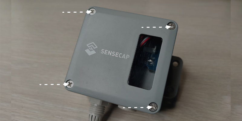
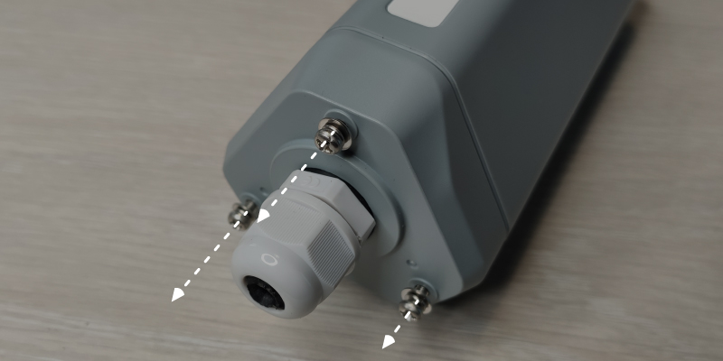
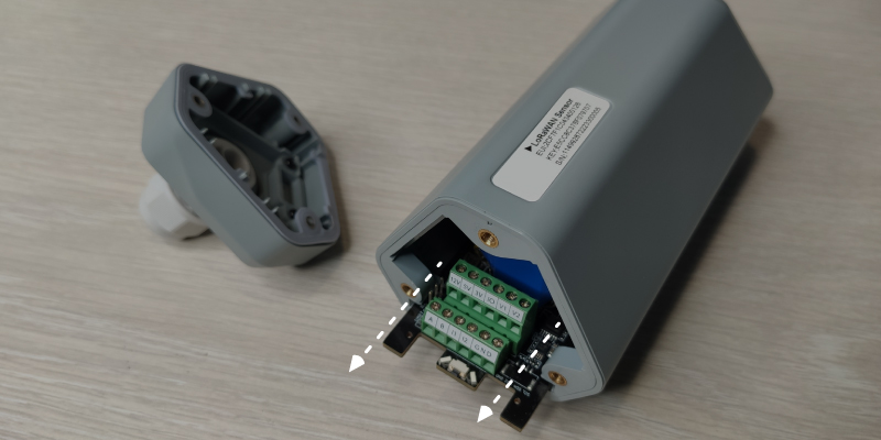
- Step 1: Unscrew the four screws on the SenseCAP S2110 Converter lid and open the lid
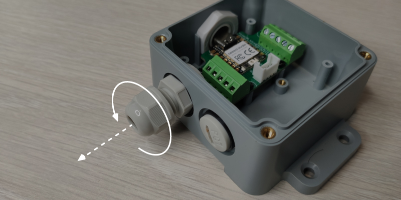
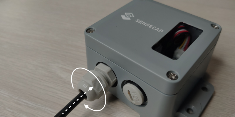
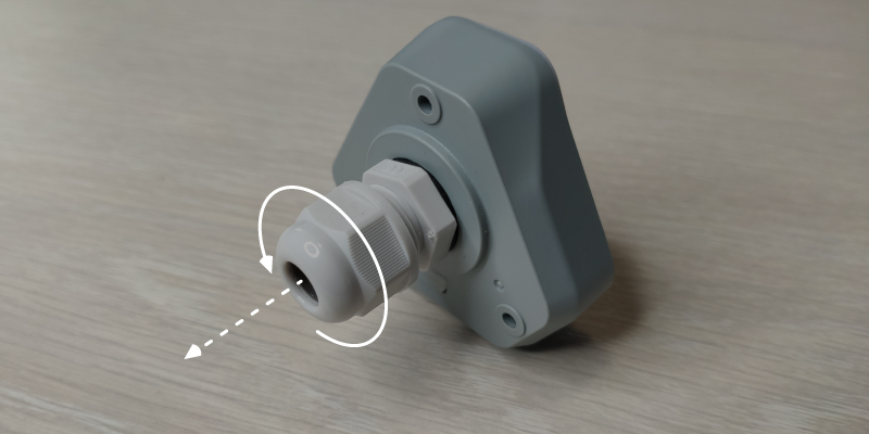
- Step 2: Remove the thread cap
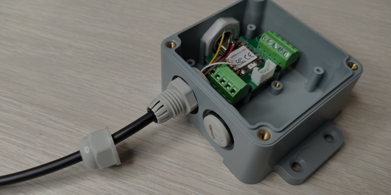
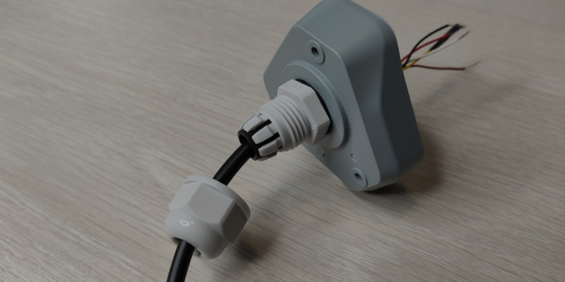
- Step 3: Pass the included cable through the cap into the SenseCAP S2110 Converter
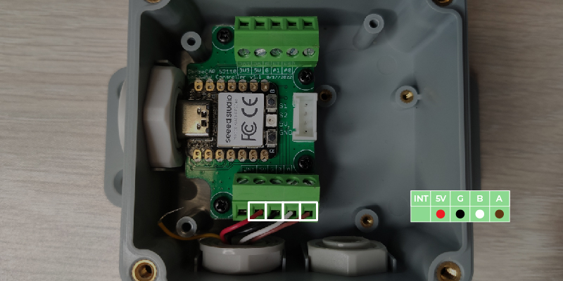
- Step 4: Connect the wires of the cable into the screw terminal as follows
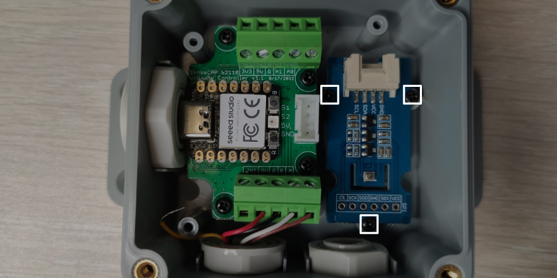
- Step 5: Place a Grove sensor inside the SenseCAP S2110 Converter and screw it
Grove with 2 holes (ex: Grove - Light Sensor v1.2)
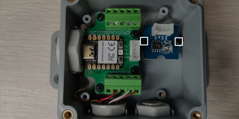
Grove with 3 holes (Grove Temperature and Barometer Sensor (BMP280))
- Step 6: Connect Grove cable to Grove sensor and Grove connector on SenseCAP S2110 Converter board

- Step 7: Close lid and screw it back
- Step 8: Tighten the thread cap and secure in place
Connect SenseCAP S2110 Converter to SenseCAP Data Logger
- Step 1: Uncrew the three screws on the data logger
- Step 2: Remove the bottom cover and take out the inside PCBA until the screw terminals are accessible. You do not need to take out the entire board
- Step 3: Remove the thread cap by unscrewing in clockwise counter-clockwise direction
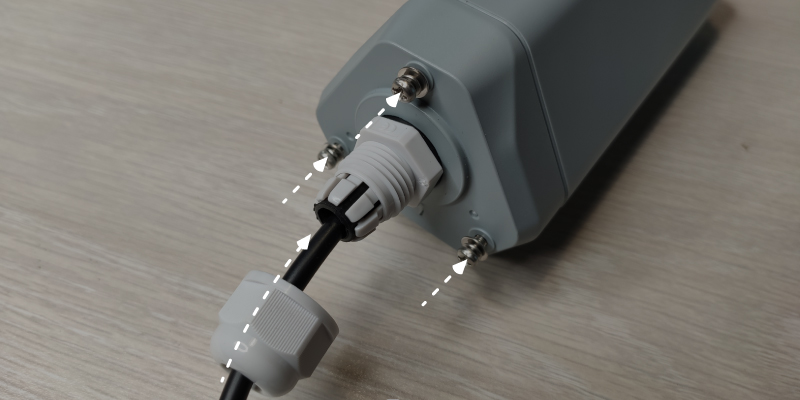
- Step 4: Pass the included cable through the thread cap and the bottom cover
- Step 5: Connect the wires of the cable into the screw terminal as follows
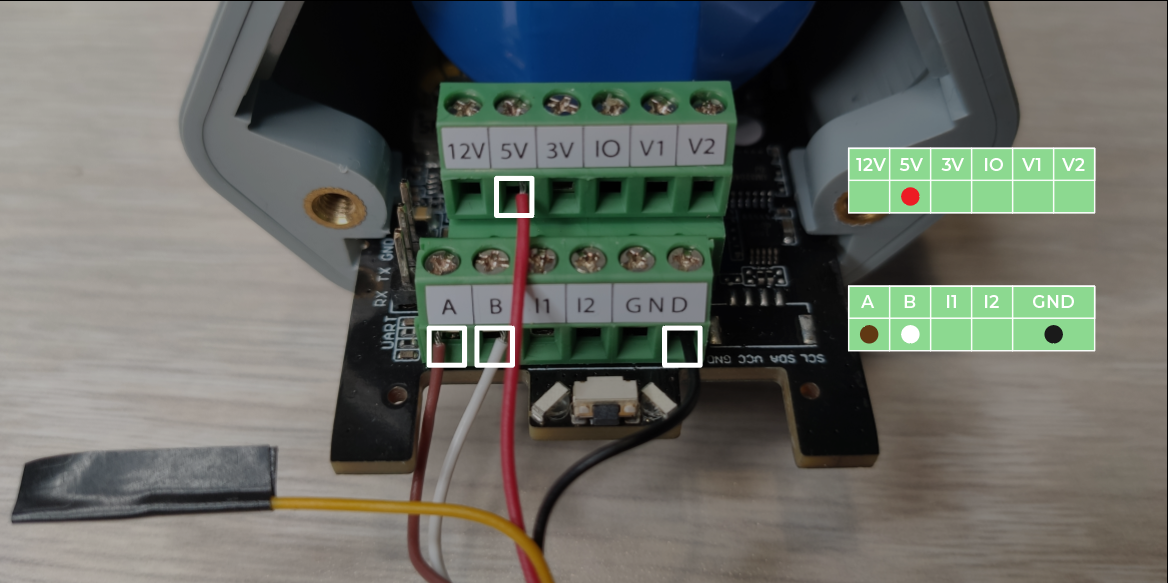
Note: Since there are 5 wires inside the cable and we are only using 4, it is better to tape the extra wire to avoid accidental contacts with the screw terminals
- Step 6: Put back the hardware unit inside the case, close it from bottom cover and screw it back
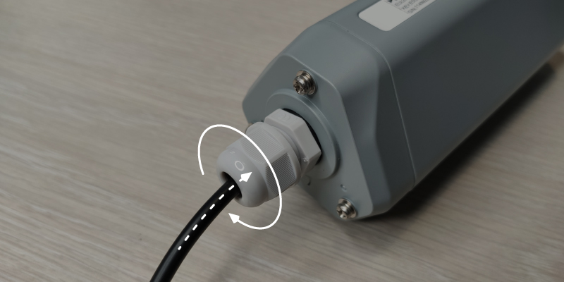
- Step 7: Tighten the thread cap and secure the cable in place
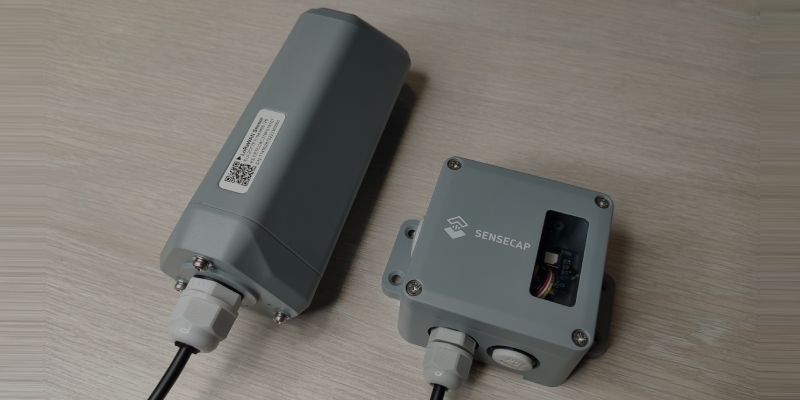
Once all the connections are done for the SenseCAP S2110 Converter and the Data Logger, it should look like below
Connect to SenseCAP Cloud via SenseCAP Mate App
Download, Install SenseCAP Mate App and Log In
Step 1: Download and install SenseCAP Mate App on your mobile phone according to your OS
Step 2: Open the SenseCAP Mate APP and sign in to your SenseCAP account by entering your registered email and password and clicking Login buttons

Note: Keep the Server Location as Global, which is the default
If it is your first time to use the SenseCAP platform, please register an account first by clicking Register button and login afterwards with the newly created account
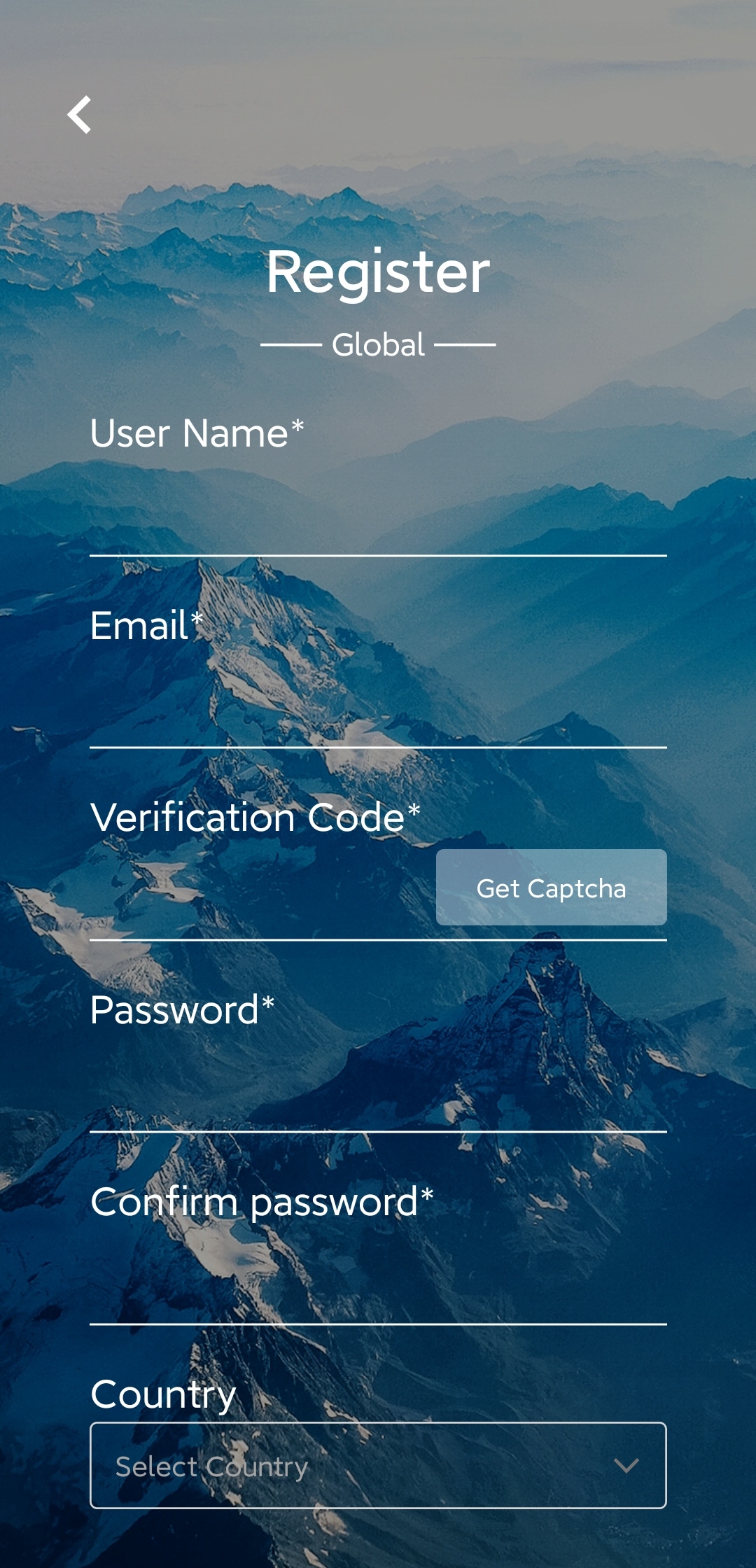
Note: The fields with are required fields, and those without can be filled in optionally.
Update Data Logger Firmware
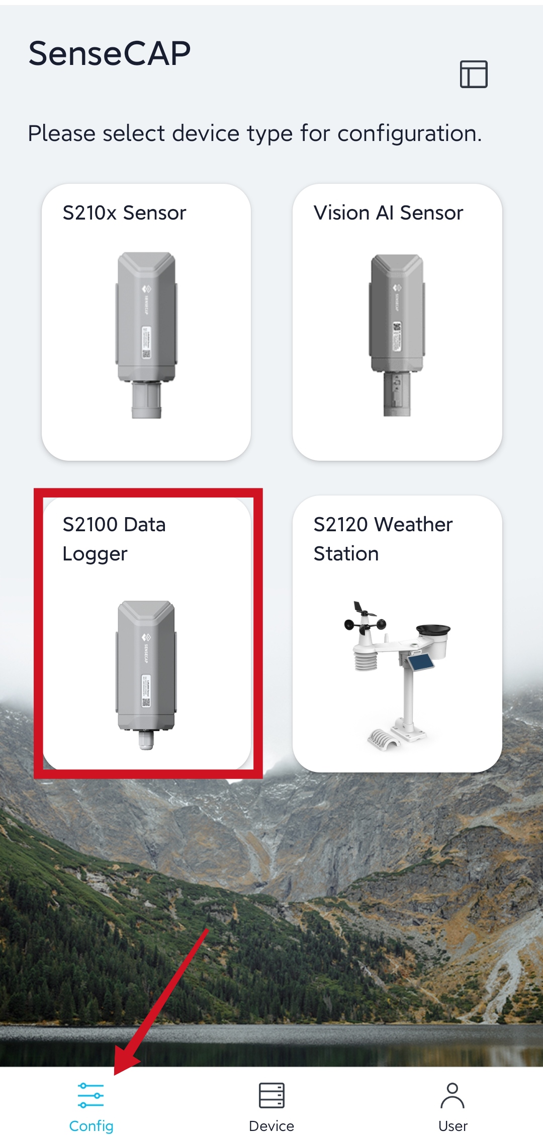
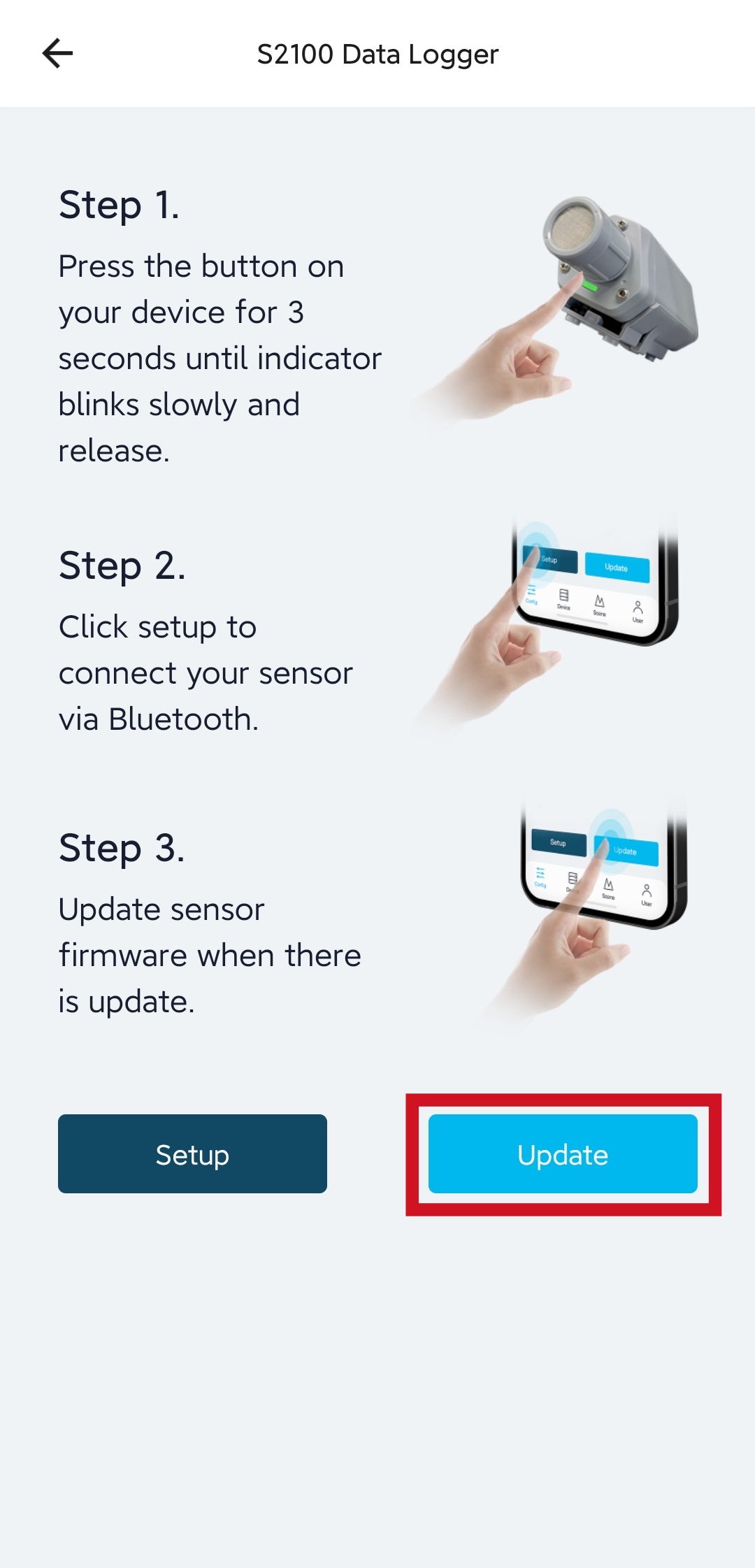
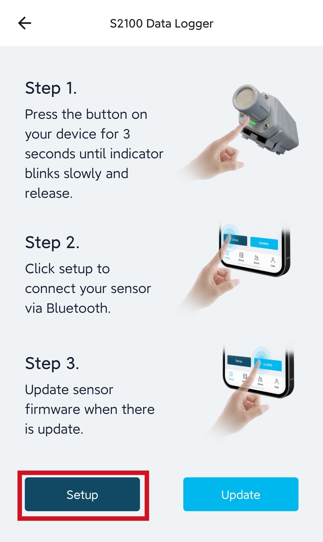
- Step 1: Under Config page, select S2100 Data Logger
- Step 2: Press and hold the configuration button on the SenseCAP Data Logger for 3 seconds to enter bluetooth pairing mode
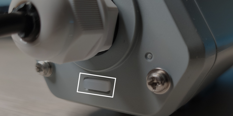
If it enters bluetooth pairing mode, a green LED will start to blink
- Step 3: Click Update
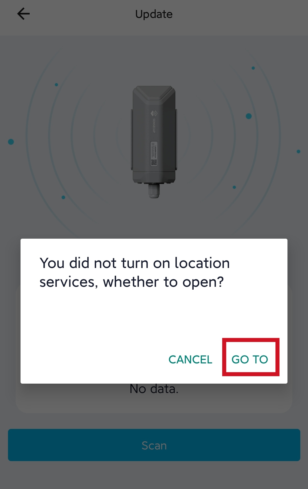
- Step 4: Now it will prompt you to turn on location services. Click GO TO to open the location services page on your phone
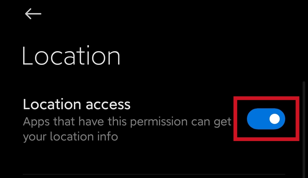
- Step 5: Turn on location services. It will look as follows for Android
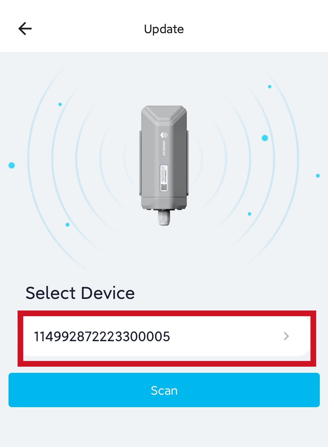
- Step 6: Come back to SenseCAP Mate App and click Scan
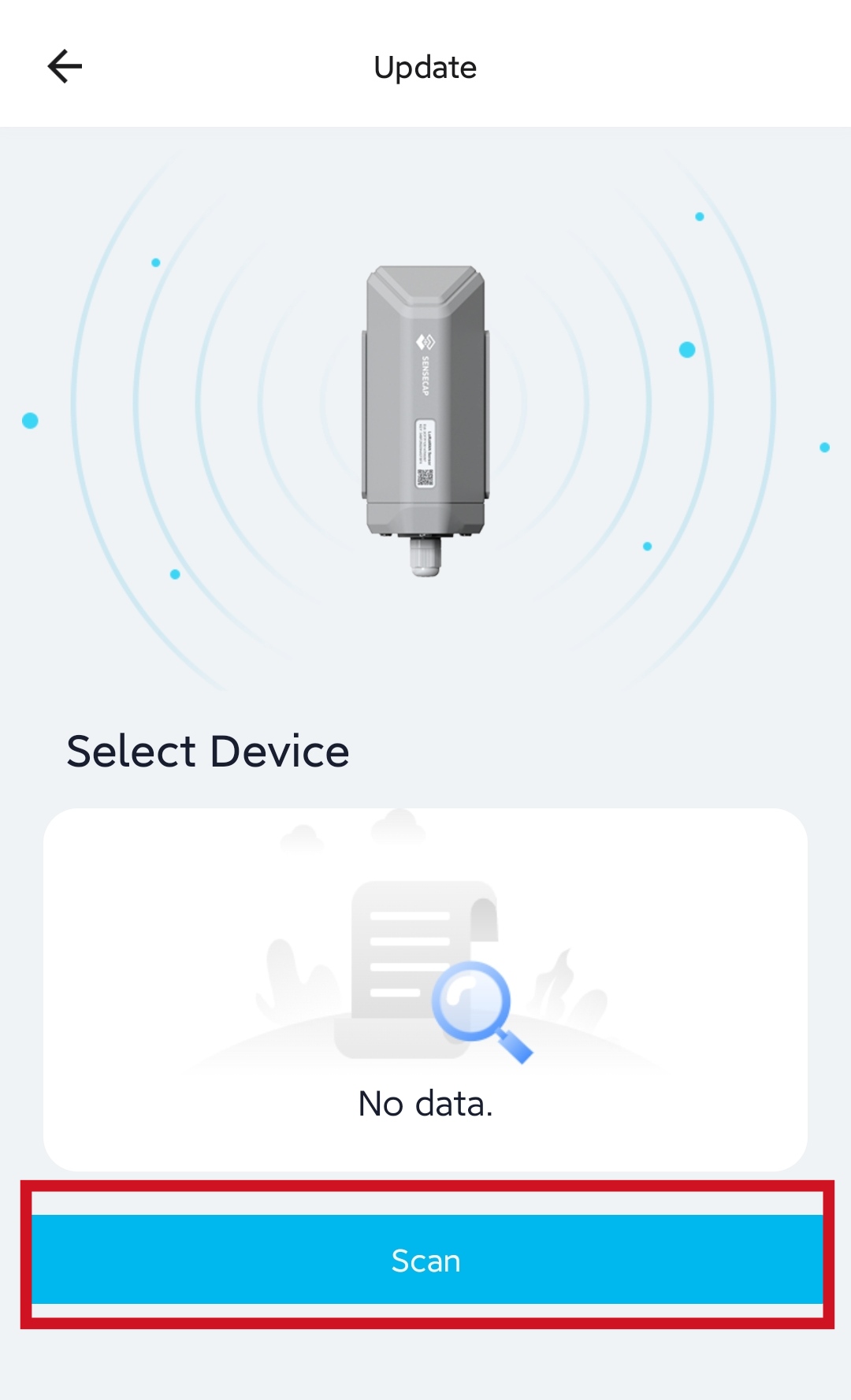
Now it will start scanning for nearby SenseCAP Data Loggers
- Step 7: Click on the discovered device
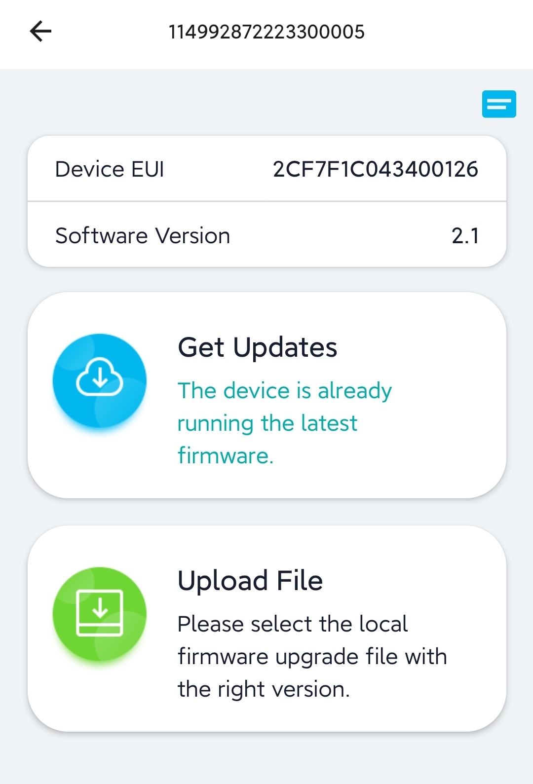
- Step 8: If an update is available, click Get Updates to update to the latest version. After updating to the latest version or if it says The device is already running the latest firmware, go back to the previous set up page
Configure Settings for Data Logger and SenseCAP S2110 Converter Communication
- Step 1: Enter bluetooth pairing mode on the Data Logger again and click Setup
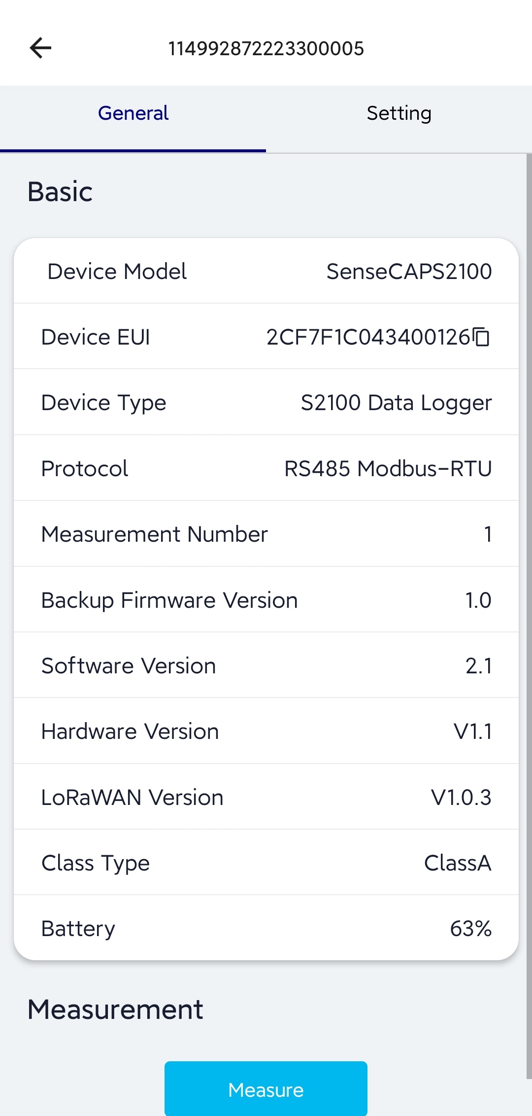
- Step 2: Click on the device found

It will open a page with useful information under General
- Step 3: Go to Setting page and under Basic Setting, choose the platform either as SenseCAP for the Things Network or SenseCAP for Helium
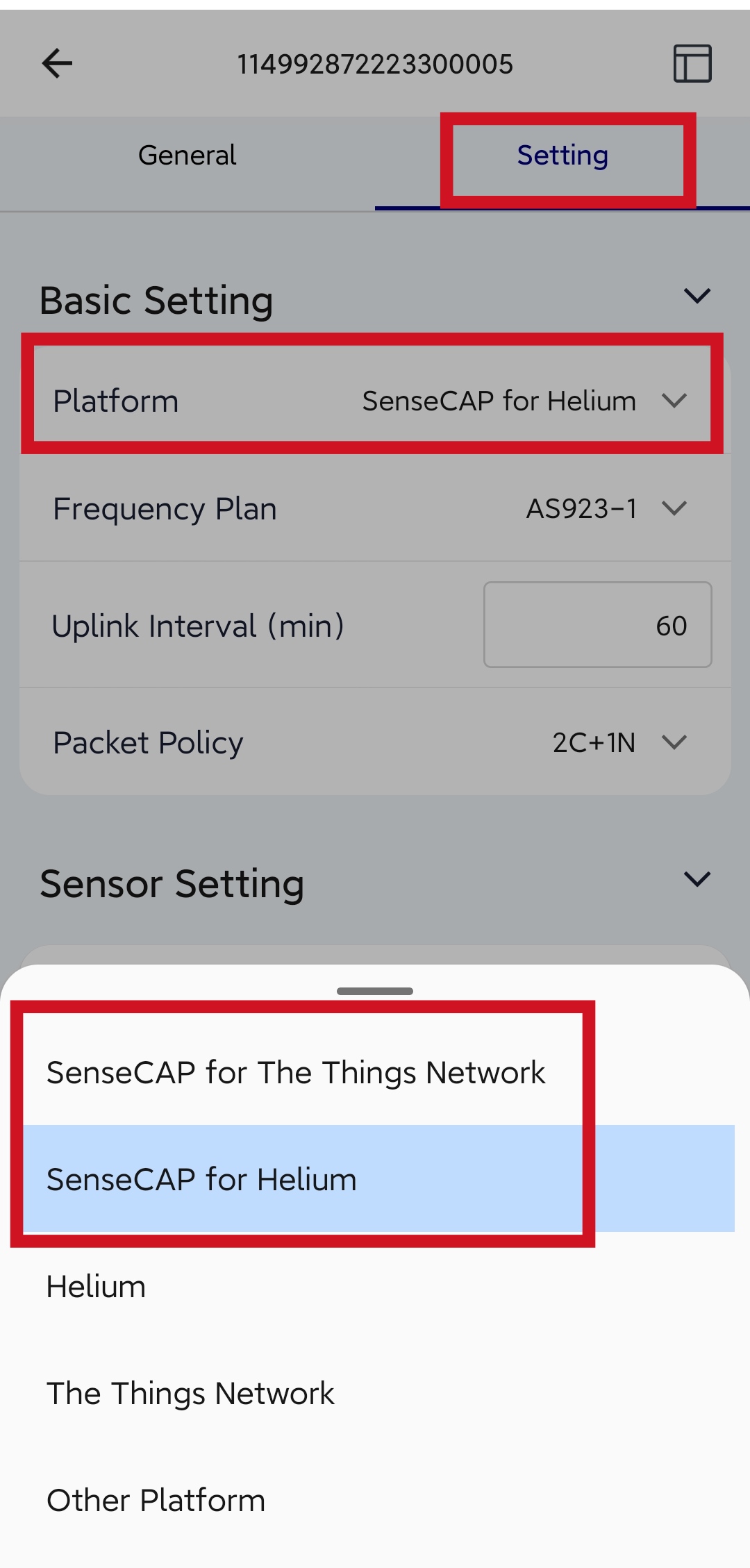
Note: You can choose others as well, but in that case, you cannot use SenseCAP platform
- Step 4: Choose the Frequency Plan, Uplink interval and Packet Policy
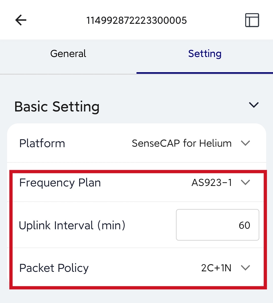
Note: The default Packet Policy is 2C+1N and the below table explains more about it and others
| Parameter | Description |
|---|---|
| 2C+1N (default) | 2C+1N (2 confirm packets and 1 none-confirm) is the best strategy, the mode can minimize the packet loss rate, however the device will consume the most data packet in TTN, or date credits in Helium network. |
| 1C | 1C (1 confirm) the device will sleep after get 1 received confirm packet from server. |
| 1N | 1N (1 none-confirm) the device only send packet and then start to sleep, no matter the server received the data or not. |
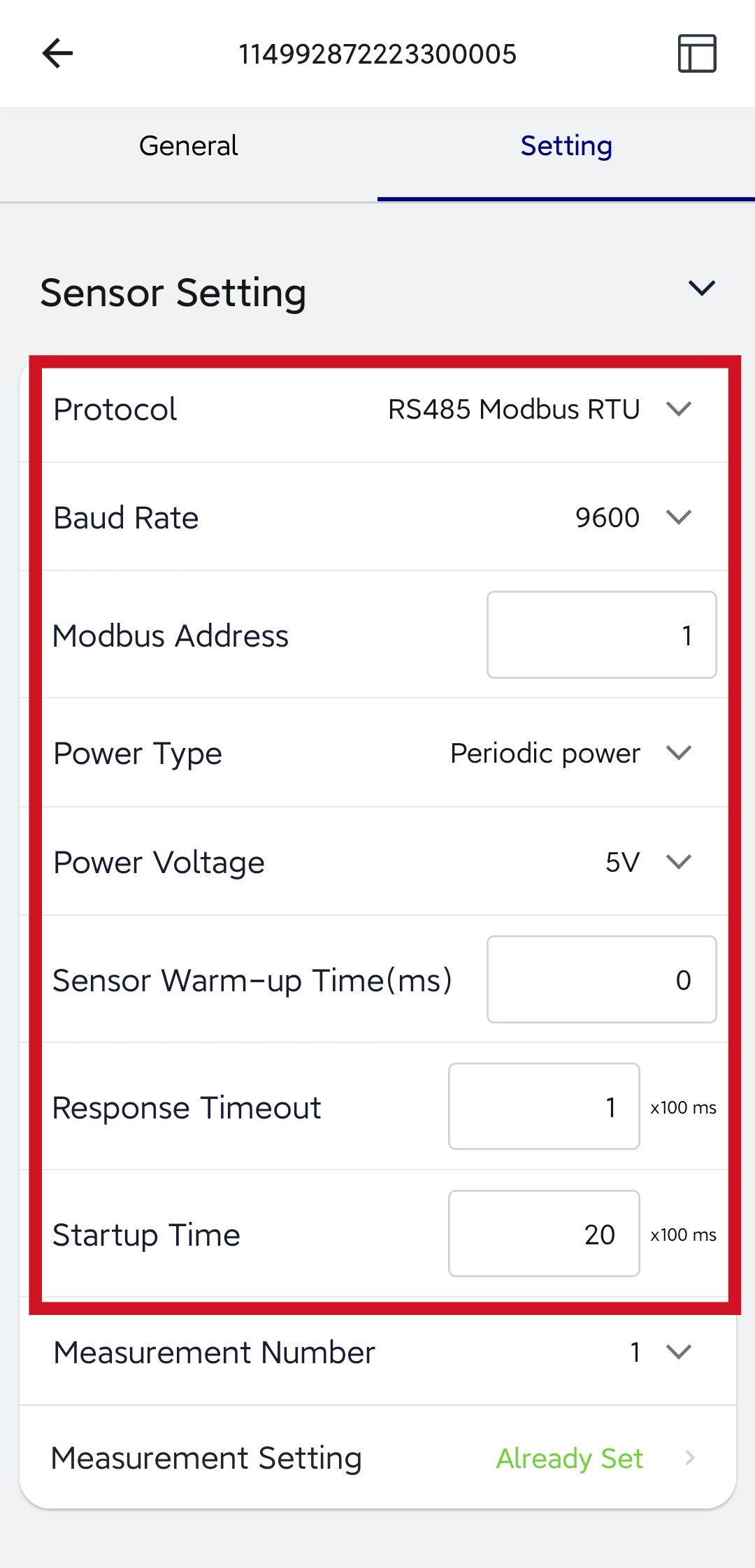
- Step 5: Under Sensor Setting, fill as follows
| Parameter | Description |
|---|---|
| Protocol | RS485 Modbus RTU |
| Baud Rate | Baud rate of communication with the sensor. Select 9600 here. |
| Modbus Address | Slave address of the sensor. The range is 1 to 247. Enter 1 here. |
| Power Type | Periodic power: Power the sensor before data collection, and power off the sensor after data collection. This mode reduces power consumption and increases battery life. Always-on: Select this mode when the sensor needs constant power supply. Generally, an external 12V DC power supply is used. If it is powered only by batteries, it may not work for long. Select periodic power here. |
| Power Voltage | Select the supply voltage to the sensor. It supports 3V/5V/12V. Select 5V here. |
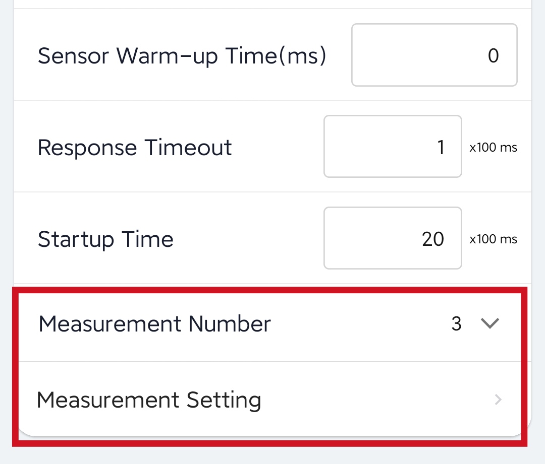
| Sensor Warm-up Time | The warm-up time denotes the amount of time it takes for the sensor to attain its highest accuracy or performance level once the voltage supply has been applied. This depends from sensor to sensor. Only the Grove - Oxygen Sensor (MIX8410) needs a warm-up time of 5s, which means you need to enter 5000 inside the box. The other Grove sensors supported by the SenseCAP S2110 Converter at the moment only need 0ms warm-up time. |
| Response Timeout | After Data Logger initiates a data read request to the sensor, it waits for the timeout time for a response. If this time is exceeded, the command will be resent. Enter 1 here, which means 100ms. |
| Startup Time | The length of time the sensor can communicate from powered -on to communicating with Modbus. Enter 20 here, which means 2000ms=2s |
A filled settings page can be seen below
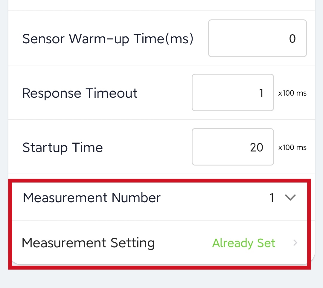
- Step 6: For the Measurement Number, refer to the table below according to the specific sensor.
| Grove Sensor Name | Measure Number |
|---|---|
| Grove - Light Sensor v1.2 | 1 |
| Grove - Flame Sensor | 1 |
| Grove - Oxygen Sensor (MIX8410) | 1 |
| Grove - CO2 & Temperature & Humidity Sensor (SCD41) | 3 |
| Grove - Sunlight sensor (SI1151) | 3 |
| Grove Temperature and Barometer Sensor (BMP280) | 3 |
Note: SenseCAP Data Logger can collect 0 to 10 measurements in RS485 mode.
- Step 7: After specifying the Measurement Number, you need to fill the Measurement Settings. Here we will choose a Grove - Light Sensor v1.2. For this sensor, we only need one measurement, which is the light level. Select 1 for the Measurement Number and click Measurement Setting
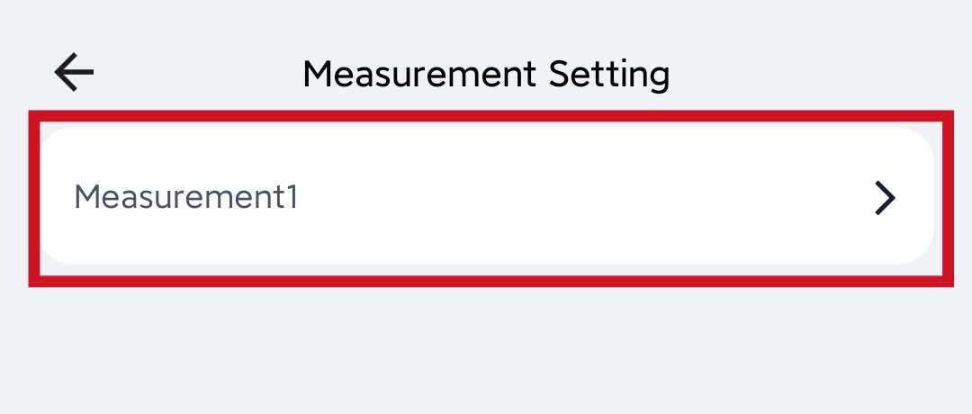
- Step 8: Under Measurement Setting click Measurement1
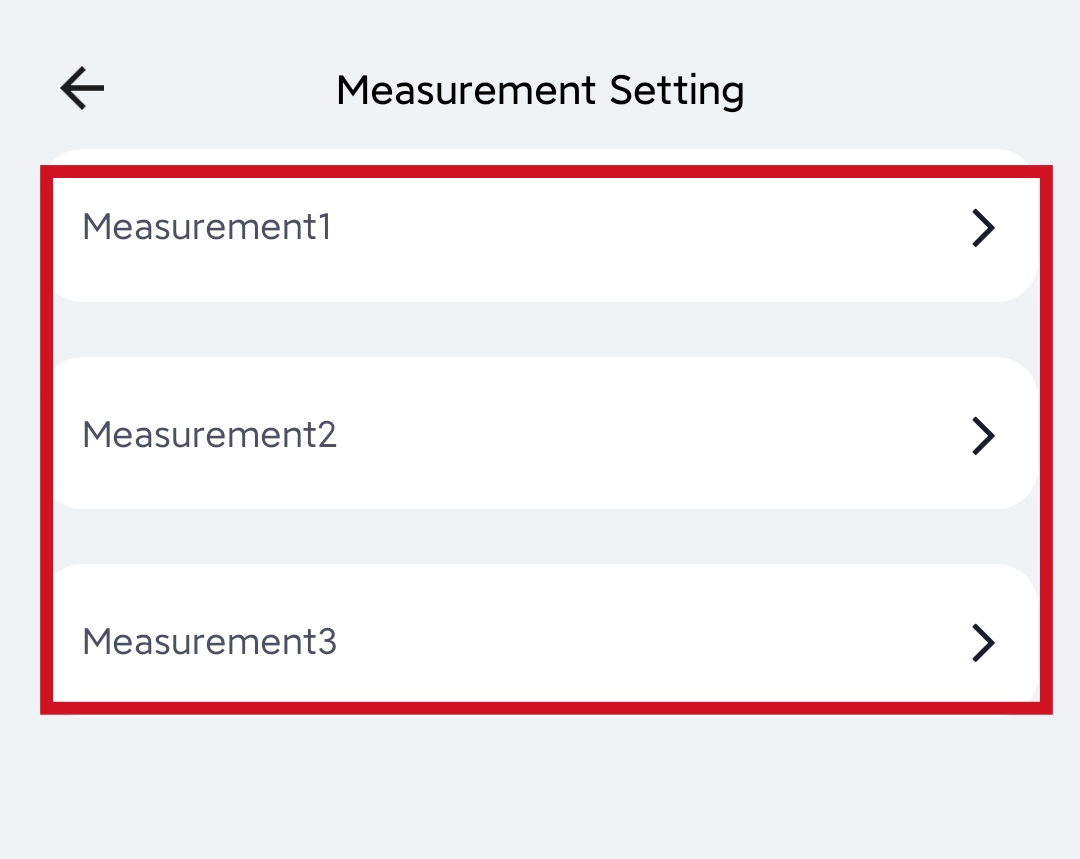
If you use the Grove - CO2 & Temperature & Humidity Sensor (SCD41) we need three measurements, which is the temprature, humidity and C02 levels. Select 3 for the Measurement Number and click Measurement Setting
Also, here you need to configure the 3 measurements separately
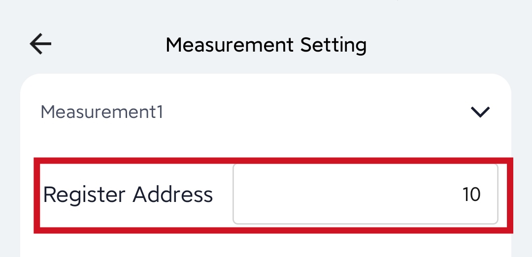
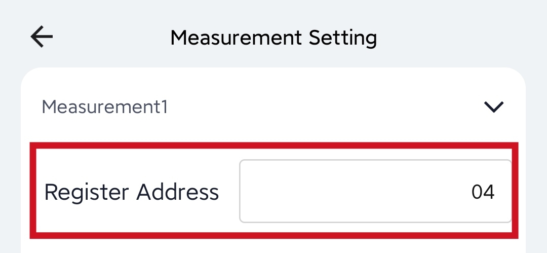
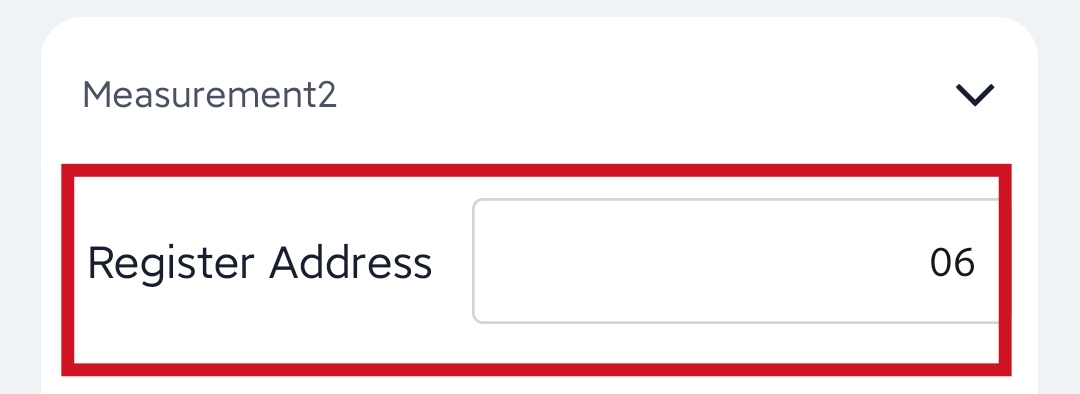
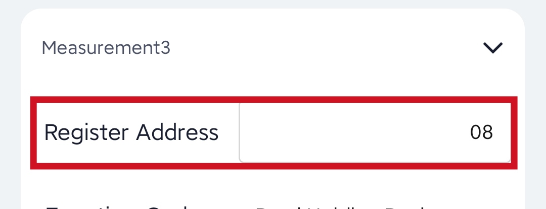
- Step 9: For the Register Address, refer to the table below and enter the decimal value of the register address
| Grove Sensor Name | Register Name | Register Address (Hexadecimal) | Register Address (Decimal) |
|---|---|---|---|
| Grove - Light Sensor v1.2 | Light | 0x000A | 10 |
| Grove - Flame Sensor | Flame | 0x000C | 12 |
| Grove - Oxygen Sensor (MIX8410) | Oxygen | 0x000E | 14 |
| Grove - CO2 & Temperature & Humidity Sensor (SCD41) | Temperature | 0x0004 | 04 |
| Humidity | 0x0006 | 06 | |
| CO2 | 0x0008 | 08 | |
| Grove - Sunlight sensor (SI1151) | Light Intensity | 0x0010 | 16 |
| Visible Light | 0x0012 | 18 | |
| UV | 0x0014 | 20 | |
| Grove Temperature and Barometer Sensor (BMP280) | Barometric Temperature | 0x0016 | 22 |
| Atmospheric Pressure | 0x0018 | 24 | |
| Height | 0x001A | 26 |
A filled register address for the Grove - Light Sensor v1.2 can be seen below
Filled register addresses for the Grove - CO2 & Temperature & Humidity Sensor (SCD41) can be seen below
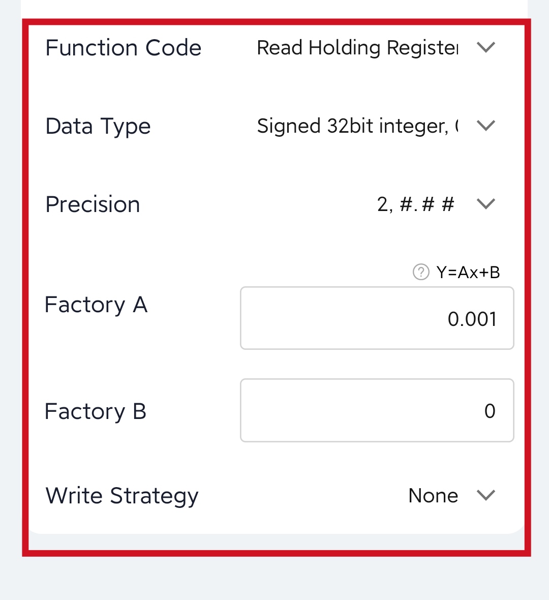
- Step 10: The rest of the settings are common to all the Grove sensors and fill them as follows
| Function Code | Modbus function code. Select 03 here |
|---|---|
| Data Type | The data type determines the number of registers read from the sensor and how the data should parse the value. Select Signed 32bit integer, 0xABCD here. |
| Precision | Precision of the value. You can choose the decimal place of the measurement value. If 1 is selected, one decimal place is reserved. Select 2, #.## here. |
| Y= Ax + B | “Y”: It is the value of Data Logger will upload. “x”: It is the original current value. Factory A: Custom values that can be scaled up or down by multiples of the “x”. Factory B: A custom value that increments or diminishes the value of the “x”. By setting the values of A and B, you can calculate the desired value. If only raw values need to be uploaded, set A=1 and B=0. Here we set Factory A is 0.001 and Factory B is 0. |
| Write Strategy | This function is enabled only for some special sensors and is generally disabled by default After reading the value of the register, special instructions can be issued to the sensor, such as the instruction to empty the register after reading register 0. None: Off by default. After Read: Send the RS485 command to sensor after reading the register. On New Data: Send the RS485 command to sensor every 24 hours. We don’t need to write strategy so we select None here |
A filled Measurement Setting page can be seen below
- Step 11: Click Confirm to save the changes and it will go back to the Setting page

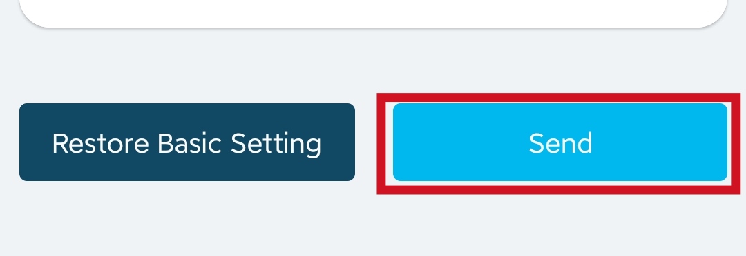
- Step 12: Click Send to send the changes to the Data Logger
Test and View the Sensor Data Locally
Now we need to test whether the SenseCAP S2110 Converter is properly sending the sensor data to the Data Logger.
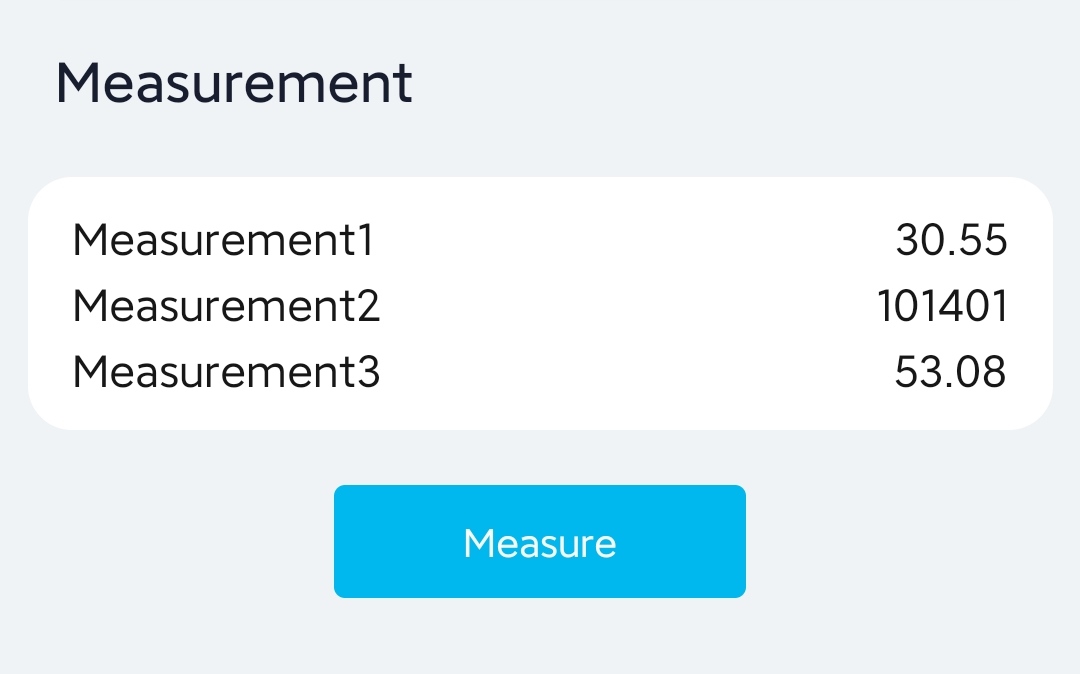
- Step 1: Go to General and click Measure
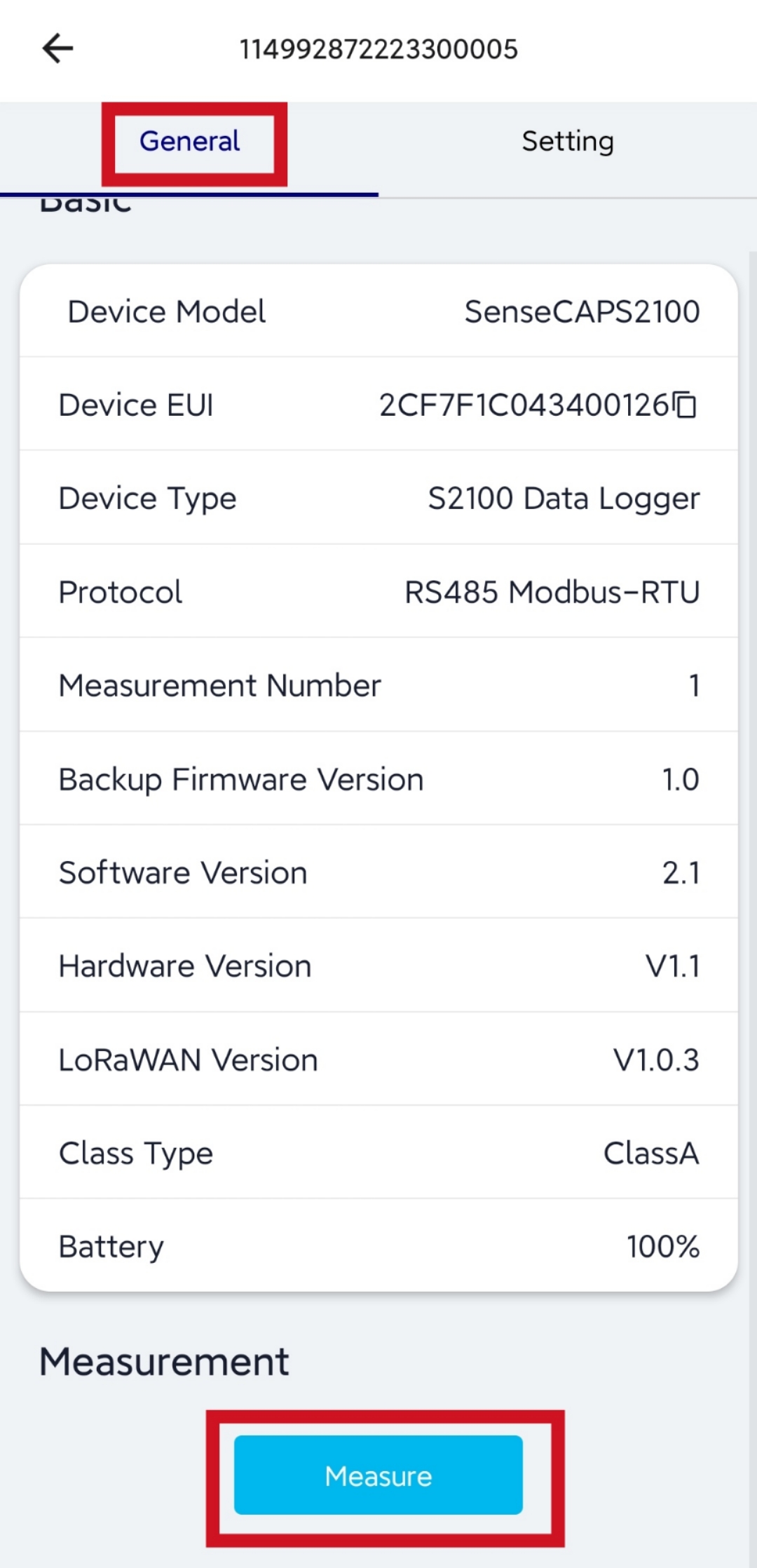
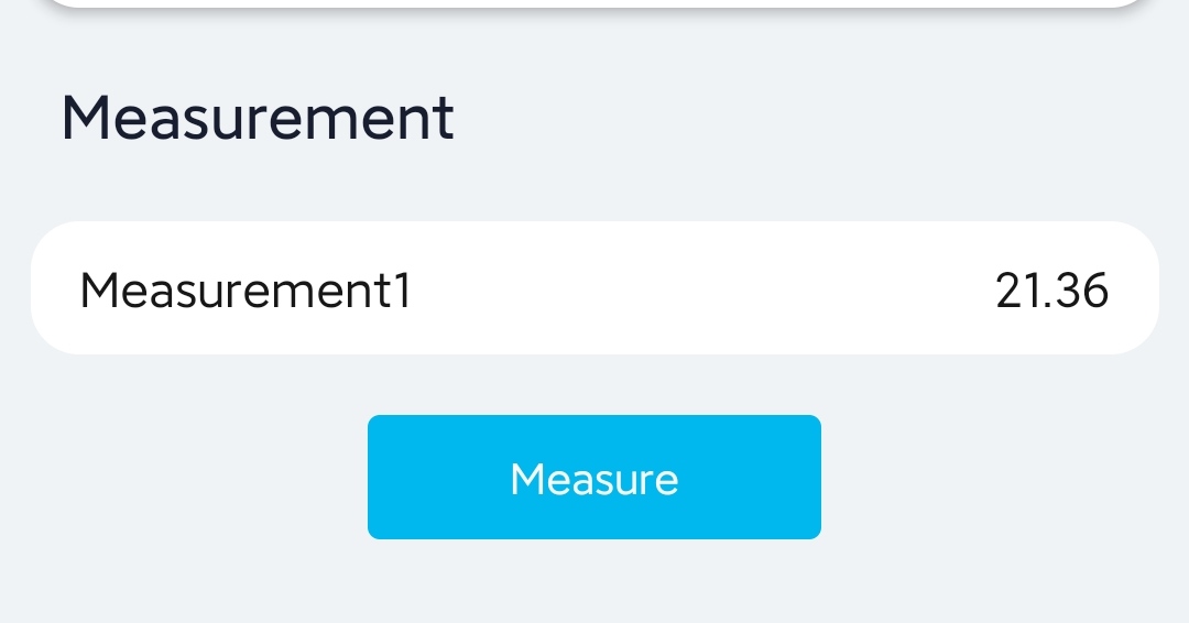
Now it will display the sensor value and you will see the LEDs of the Seeed Studio XIAO RP2040 on the SenseCAP S2110 Converter lighting up
The below is for Grove - Oxygen Sensor (MIX8410). This indicates oxygen concentration of air which is 21.36%.
The below is for Grove Temperature and Barometer Sensor (BMP280). This indicates barometric temperature as 30.55°C, atmospheric pressure as 101401Pa, and height as 53.08m.
Add Newly Created Sensor to SenseCAP Platform
- Step 1: Go back to the app home page and Data Logger Red LEDs will start blinking for a couple of seconds followed by Green LEDs blinking for a brief amount of time to indicate that the LoRaWAN connection is successful and the data is sent. Alternatively you can click the button on the data logger once, to force this data sending.
You will also see the LEDs of the Seeed Studio XIAO RP2040 on the SenseCAP S2110 Converter lighting up
Now we need to add this sensor to SenseCAP platform in order to view the data on the cloud
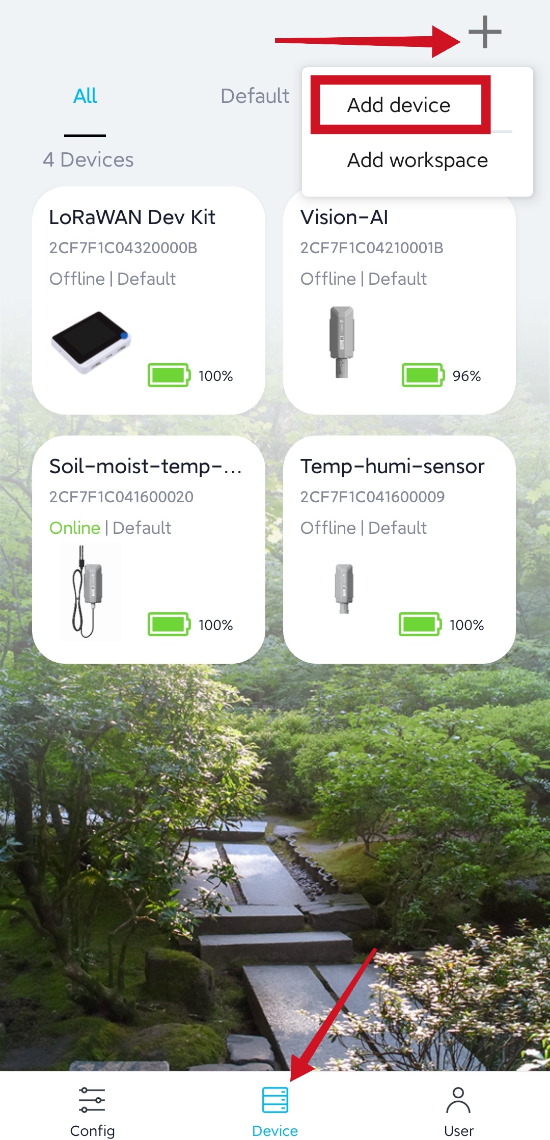
- Step 2: Go to Device page, click the + symbol and click Add device
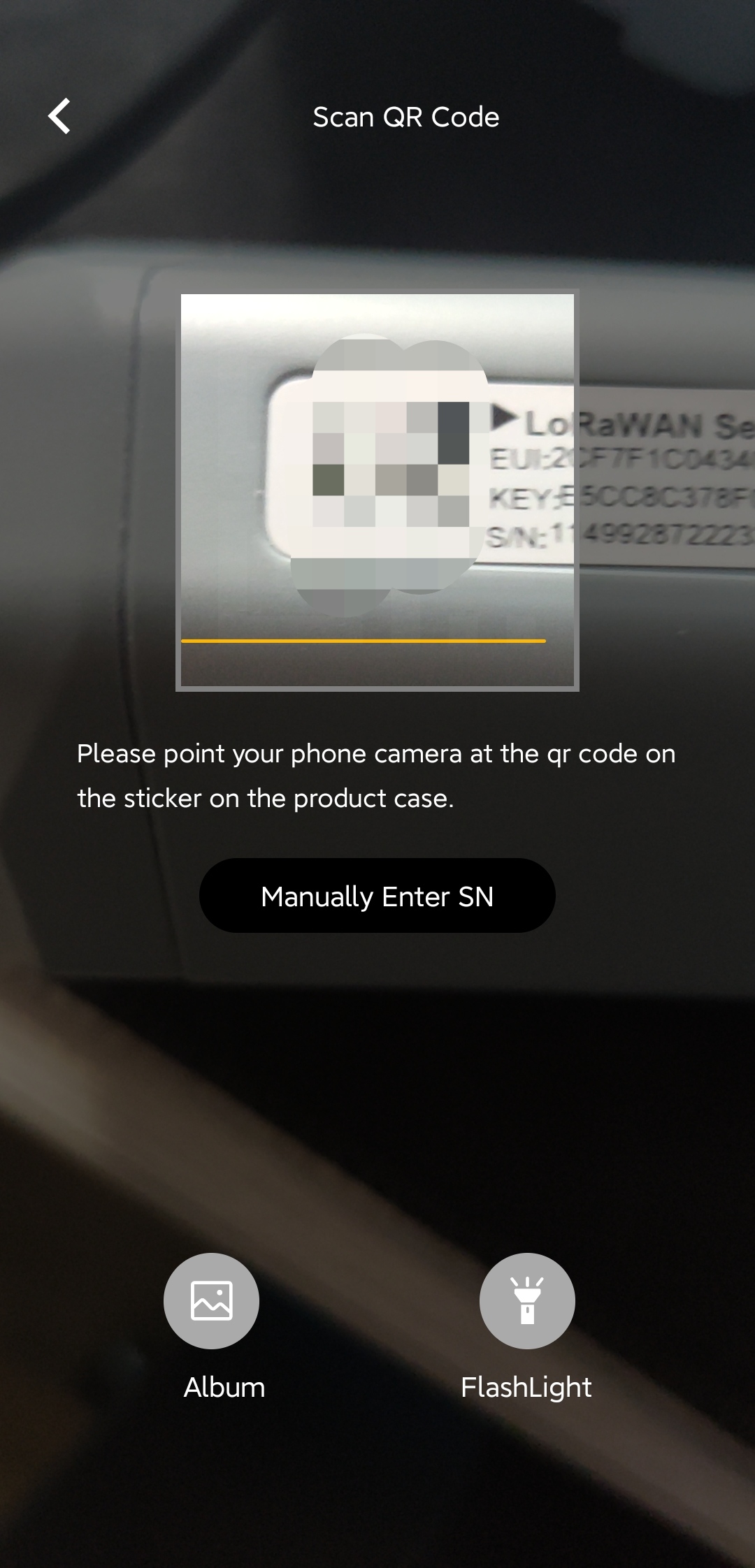
- Step 3: Scan the QR code located on the Data Logger
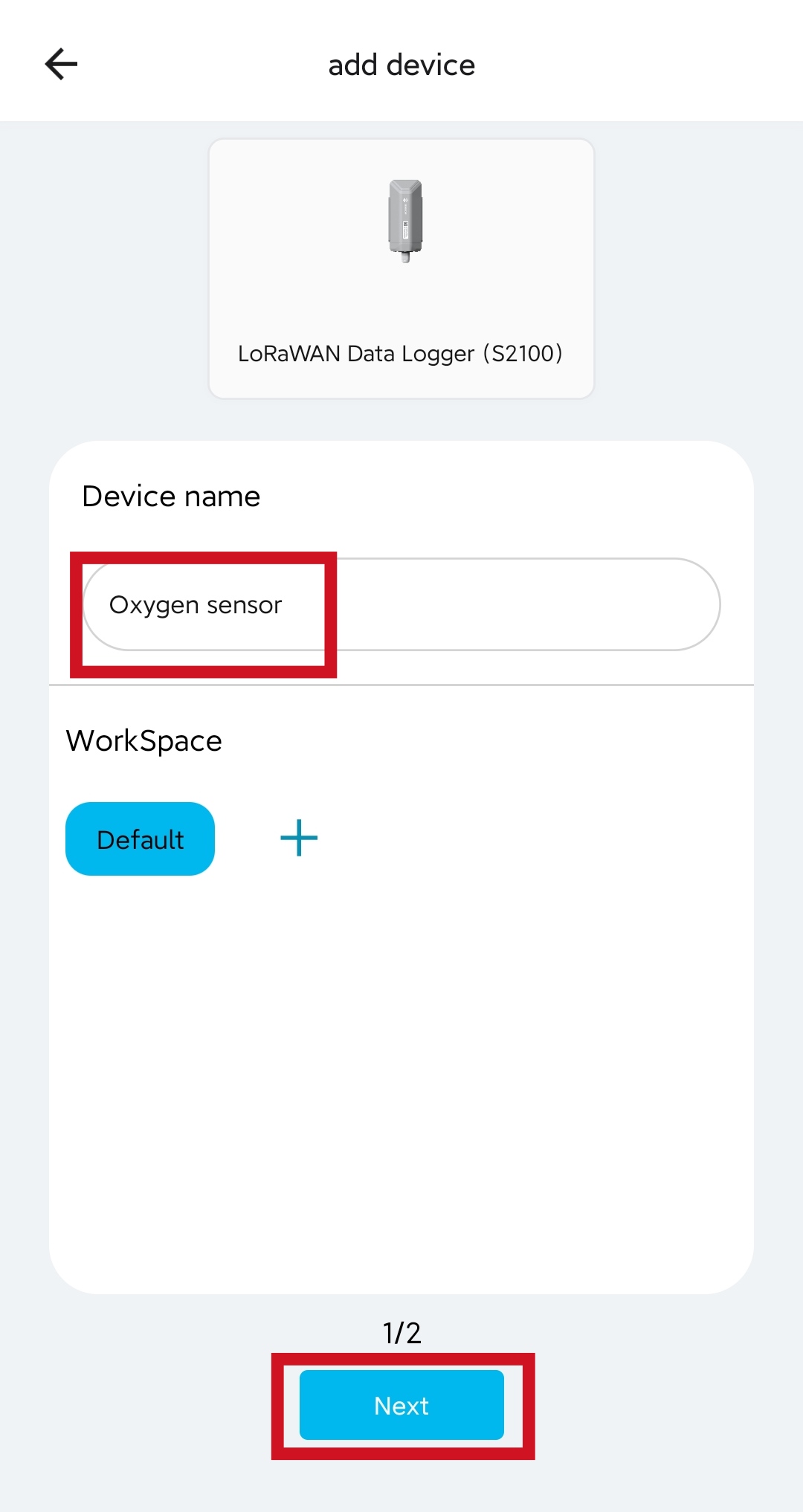
- Step 4: Enter a Device name according to the connected Grove sensor and click Next
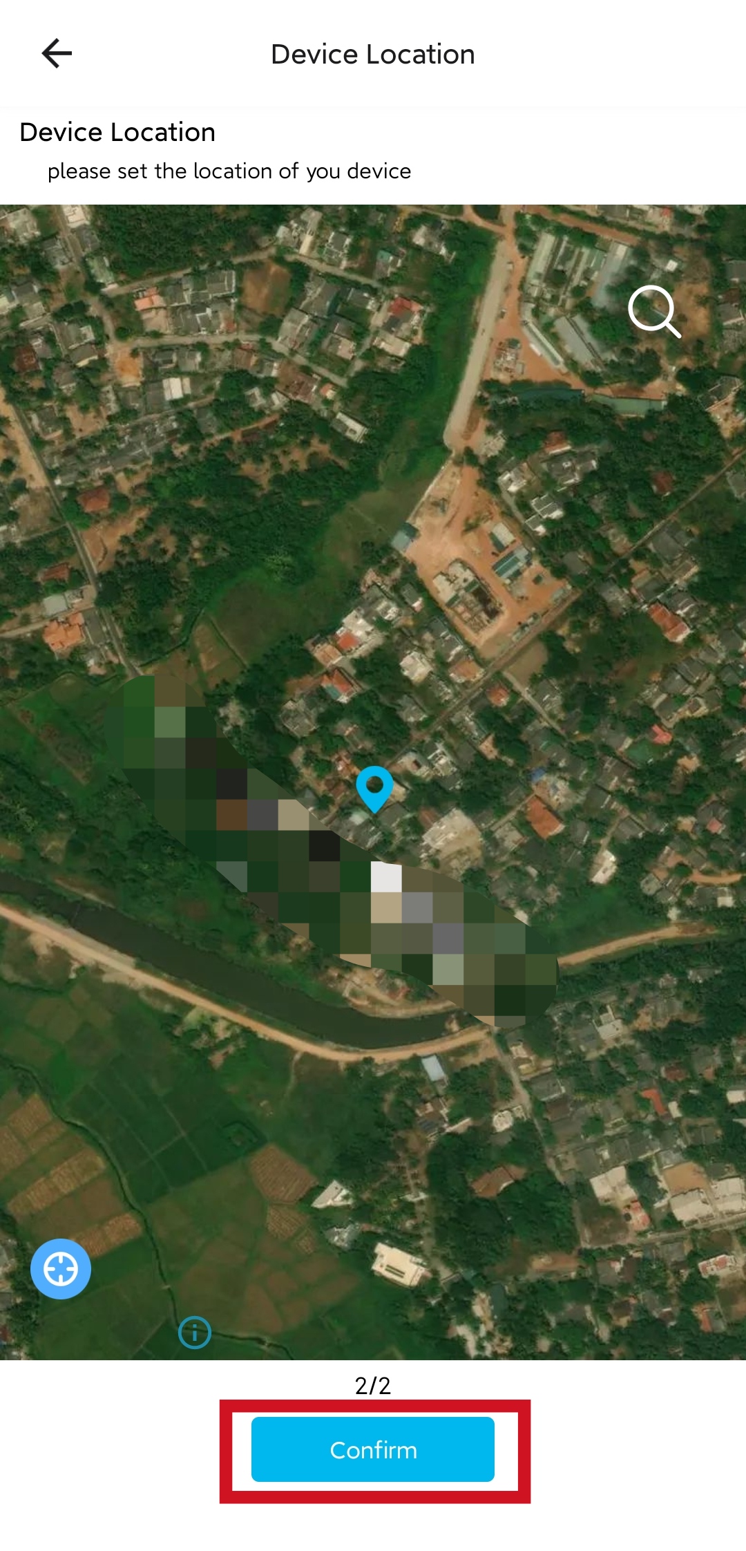
- Step 5: Enter a Device Location and click Confirm
Visualize Sensor Data on SenseCAP Mate App
Now you will see the Data Logger online on the SenseCAP Mate App
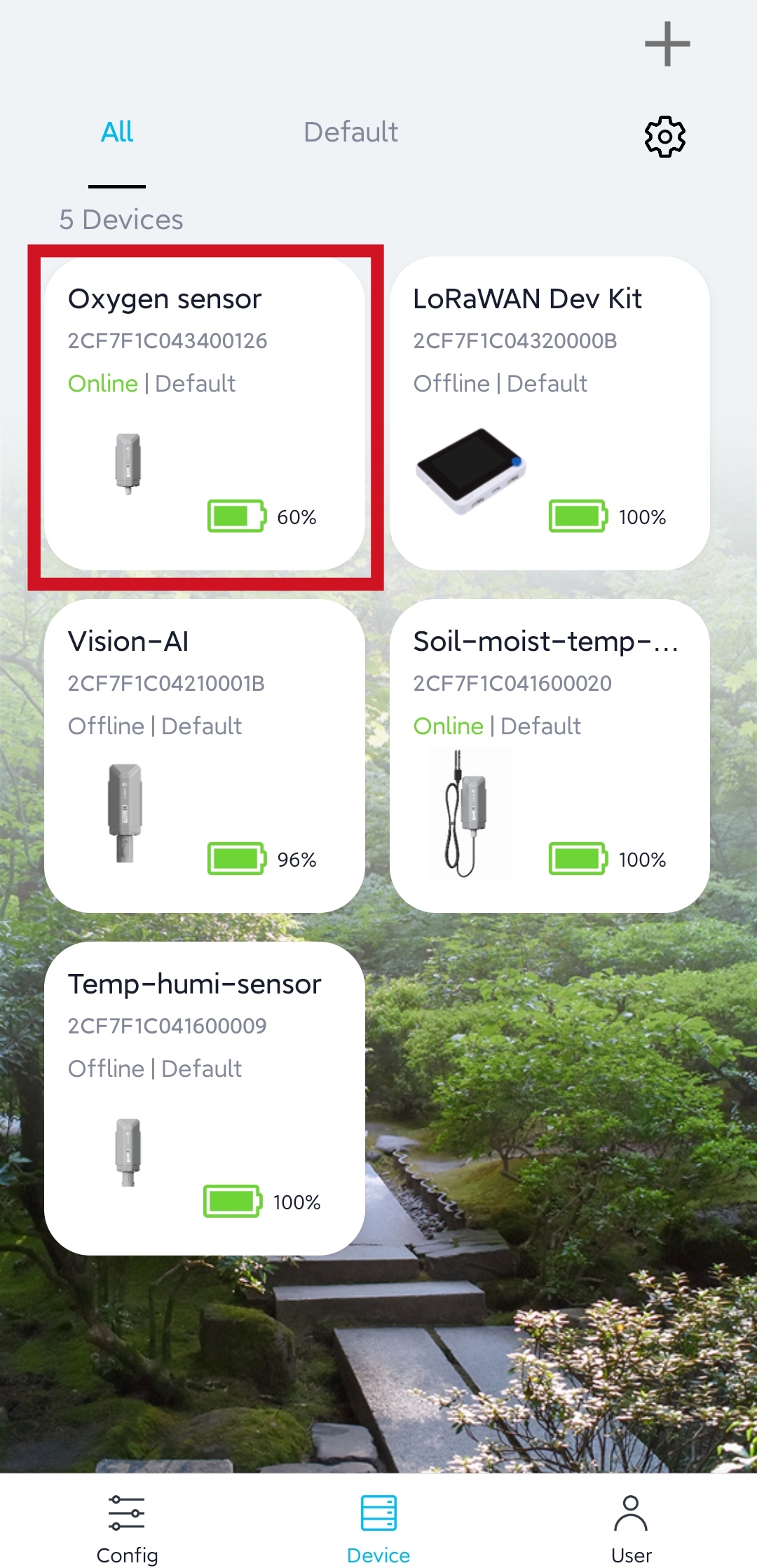
Click on it to display the sensor values
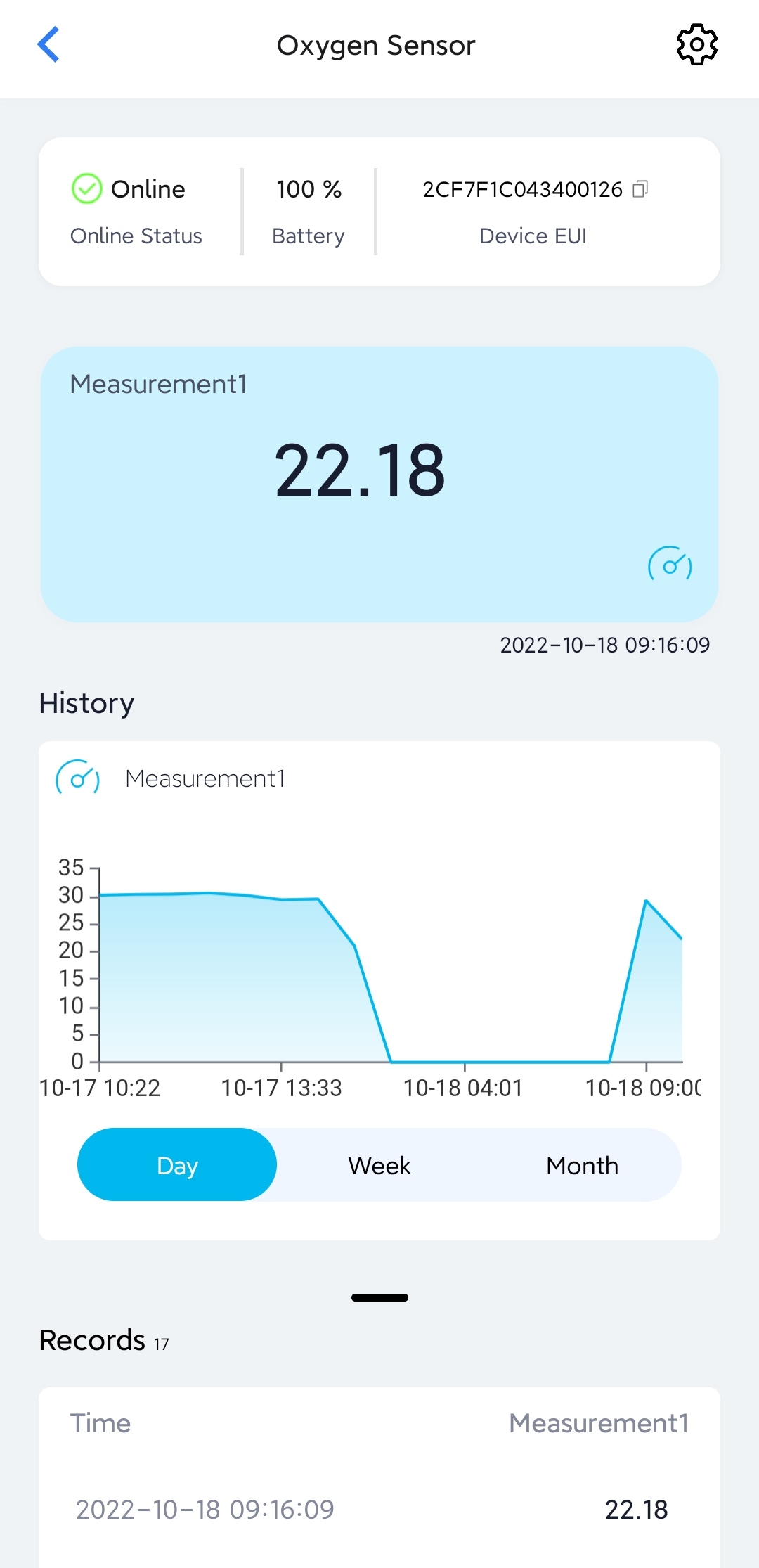
Below is for Grove Temperature and Barometer Sensor (BMP280).
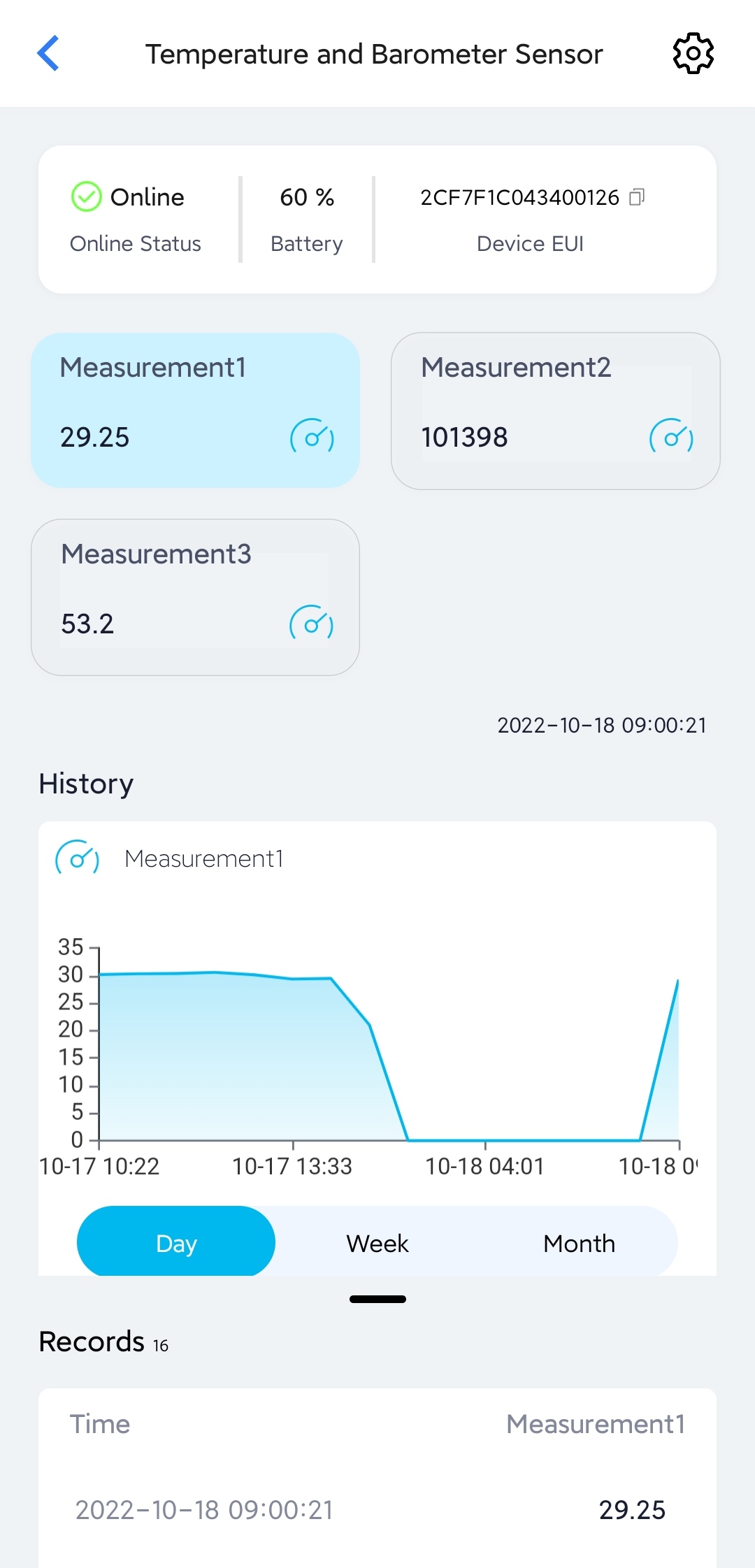
Visualize Sensor Data on SenseCAP Dashboard
You can also use the SenseCAP Web Dashboard to visualize the sensor data.
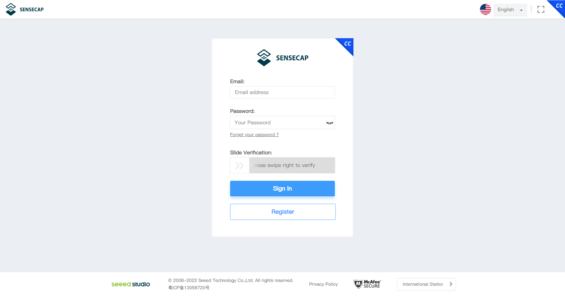
- Step 1: Visit sensecap.seeed.cc and sign in to your SenseCAP account that you created inside the SenseCAP Mate App before
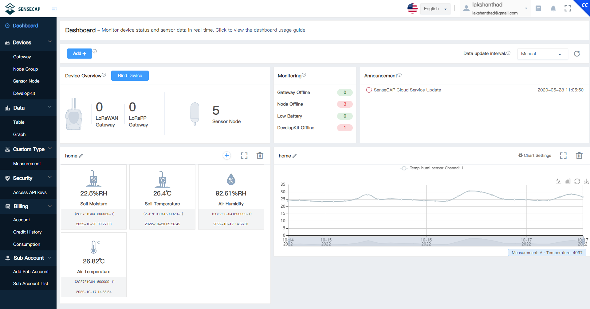
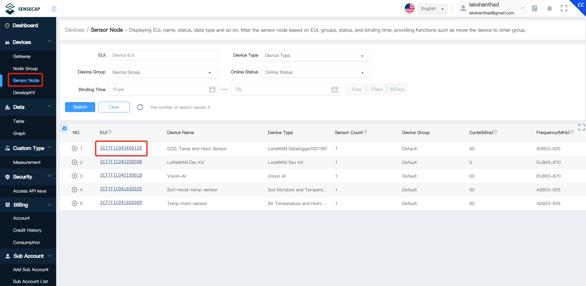
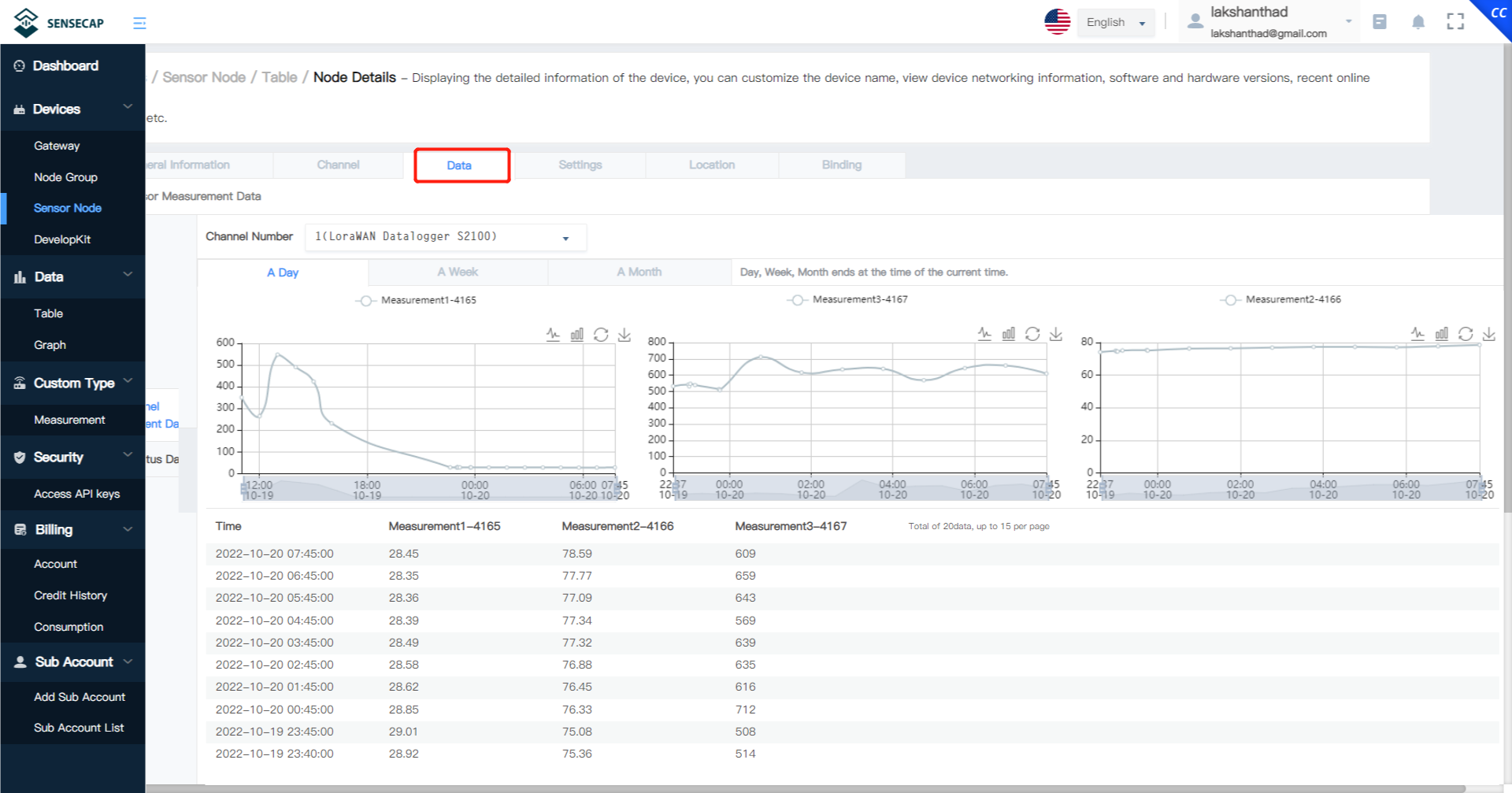
- Step 2: Click Sensor Node and select the sensor that we created before inside the SenseCAP Mate App
- Step 3: Click Data tab and you will see all sensor data displayed from the connected Grove sensor
Use as XIAO Development Board with RS485
Since there is a Seeed Studio XIAO inside, with a Grove connector as well, you can use this SenseCAP S2110 Converter as a development device just as you would normally use a XIAO with a Grove module. There is an added bonus here as well and that is, you get RS485 connectivity to add more RS485-enabled sensors to XIAO and expand your project ideas. We already have a lot of content around tinkering with XIAO and you can check this wiki to learn more.
Build Your Own LoRaWAN Grove Sensor With SenseCAP S2110 Converter and Data Logger
If you want to add more Grove sensors to the SenseCAP S2110 Converter and send the sensor data to the cloud with the help of the Data Logger, you can explore the SenseCAP S2110 Converter source code and start tinkering by yourself!
Flash Factory Firmware into SenseCAP S2110 Converter
Now we will go through the steps of flashing firmware into SenseCAP S2110 Grove to MODBUS RS485 Converter. Here we will flash the initial factory firmware.
- Step 1: Unscrew the four screws on the SenseCAP S2110 Converter lid to open the lid and unscrew the PG connector (with a coin)

- Step 2: If you have already made the connection between the SenseCAP S2110 Converter and the Data Logger with the 4 wires, it is recommended to remove the red wire which connects to the 5V pin of the SenseCAP S2110 Grove to MODBUS RS485 Converter

- Step 3: Connect one end of a USB Type-C cable to the SenseCAP S2110 Grove to MODBUS RS485 Converter. While holding down the B button, connect the other end of the USB cable to the PC to enter mass storage mode.

- Step 4: If the RPI-RP2 disk is shown on the PC and the Power LED on the XIAO is on, the connection is complete.

- Step 5: Copy controller.ino.elf.uf2 firmware file into the RPI-RP2 disk.
The RPI-RP2 disk will disappear once the firmware flashing is complete.
Resources
- [GitHub] SenseCAP S2110 Converter source code
Tech Support
Please submit any technical issue into our forum.